1. Description of the system
The Fire Damper System (FDS) allows to feed, monitor and test up to 60 fire dampers. Smoke detectors can be con-
nected and monitored, as well. The system is designed to feed only 24V fire dampers.
The system is composed of:
FDS-M FDS-S FDS-P FDS-R FDS-RB FDS-DD FDS-CD WH WK
SDD
Smoke detector
Rökdetektor
Airflow Luftflöde
Airflow Luftflöde
Master
unit
Slave
unit
Power
supply
Signal
repeater
Relay
module
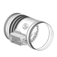
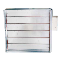
Smoke detectors Fire dampers
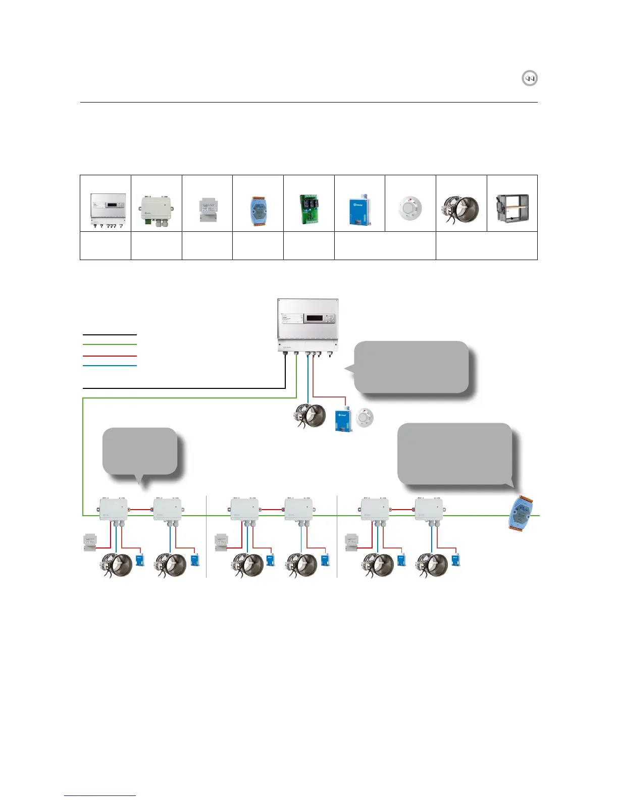
Fig. 1. FDS - Operating diagram
230 V
Communication (2 input)
24 V (2 input)
SDD
Smoke detector
Rökdetektor
Airflow Luftflöde
Airflow Luftflöde
1 FDS-P
10 FDS-S
10 WH/WK
10 FDS-CD/DD
If the communication
cable is more than 300 m,
a signal repeater, FDS-R,
is required This is also
required if the number of
FDS-S exceeds 30.
FDS-R
Signal
repeater
SDD
Smoke detector
Rökdetektor
Airflow Luftflöde
Airflow Luftflöde
SDD
Smoke detector
Rökdetektor
Airflow Luftflöde
Airflow Luftflöde
SDD
Smoke detector
Rökdetektor
Airflow Luftflöde
Airflow Luftflöde
SDD
Smoke detector
Rökdetektor
Airflow Luftflöde
Airflow Luftflöde
SDD
Smoke detector
Rökdetektor
Airflow Luftflöde
Airflow Luftflöde
SDD
Smoke detector
Rökdetektor
Airflow Luftflöde
Airflow Luftflöde
FDS-M
Master unit
4 fire dampers
4 smoke detectors
can be connected locally
to the master unit.
Communication + 24 V (4 input)