C
OK
•
•
•
7
8
2
•
3
•
•
1
1
•
•
5
6
•
4
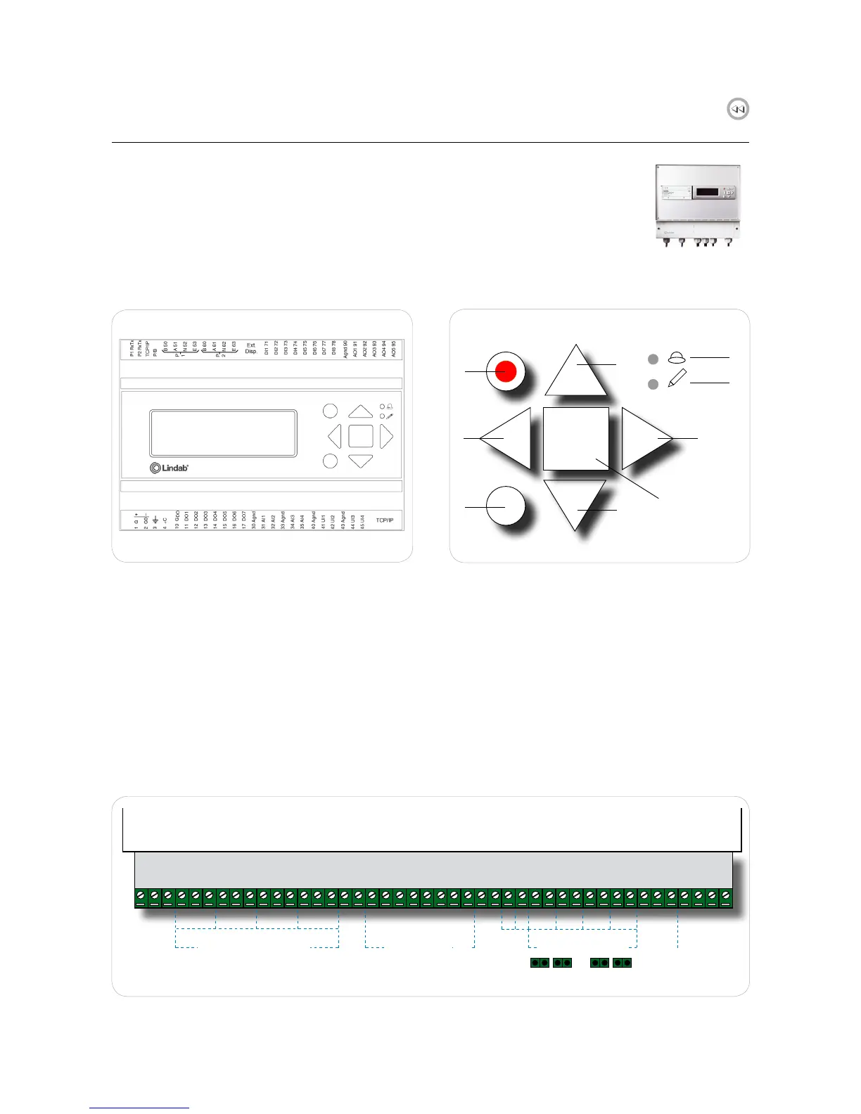
2.1 FDS-M Master unit
Fig. 2. Master unit FDS-M
1. Up/Down buttons: allows to navigate through menus
2. "Back" button: takes back to the previous page
3. "Enter" button: enter menu page
4. OK button: allows to change value
5. Red alarm LED blinks in case of alarm
6. Yellow write LED blinks when values can be changed
on current page
7. Red button: Takes to the alarm acknowledgment page
8. C button: exit value editing
FDS-M master unit is a pre-programmed controller with internal display. The display is backlit and the menus are easy
accessible and controlled by pushbuttons on the front together with two LED indicators for alarm and write indication.
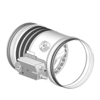
Fig. 3. PCB about FDS-M
The PCB at the bottom of the unit allows to easily wire components with no need to open the FDS-M box.
B
A
N
+C
S2 _1
S6_1
+C
S2_2
S6_2
+C
S2_3
S6_3
+C
S2_4
S6_4
AGND
A01
GD0
D01
GD0
D02
GD0
D03
GD0
D04
GD0
D05
D06
D07
+ - + - + - + -
AGND
Pt
GD0
+C
Ext1
Ext2
Ack
1 2 3 4
0-10V
SEF
\ SEF
A S
1 2 3 4
1-2
RS485
Slave unit
to A and B
SERVOMOTOR SWITCHES SERVOMOTORS
STOP AHU
ALARM
SMOKE DETECTORS
PRESSURE ALARM
1-2 1-2 1-2