Rev: 05.23.2017 Page 13 Ground Control 3.0 Service Manual
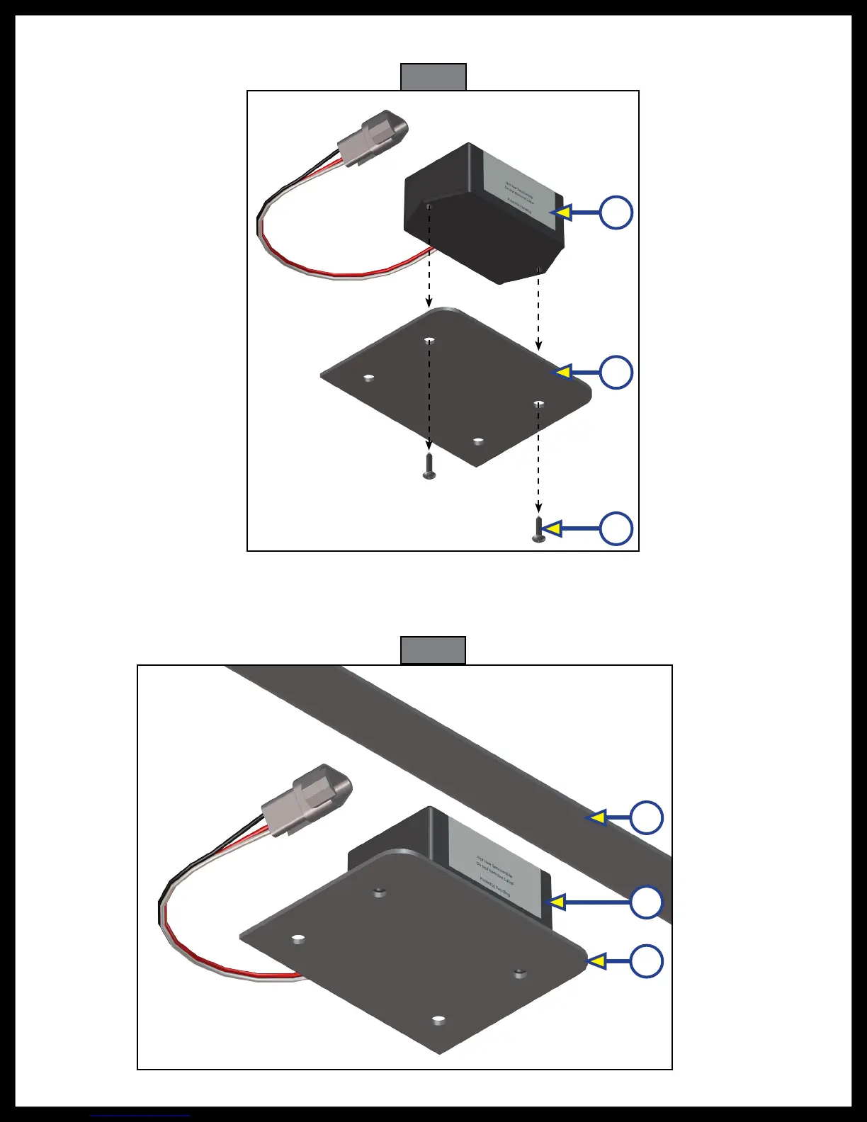
5. Remove the screws (Fig. 20C) from the rear sensor (Fig. 20A) and mounting plate (Fig. 20B) and remove
the sensor from the plate.
6. Dry fit the mounting plate (Fig. 21C) and the replacement rear sensor (Fig. 21B) to the crossmember
(Fig. 21A). The pre-drilled holes in the plate are for mounting the rear sensor to the plate. Mark on the
plate where the rear sensor will set. Space between the sensor and the crossmember must be left so
the wire harness will not be pinched.
Fig. 20
A
B
C
Fig. 21
A
B
C

 Loading...