Preparation
NOTE: All screws supporting awning assembly must have a backer within the structure of the wall of the
unit.
Installation
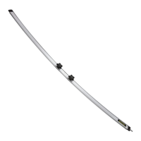
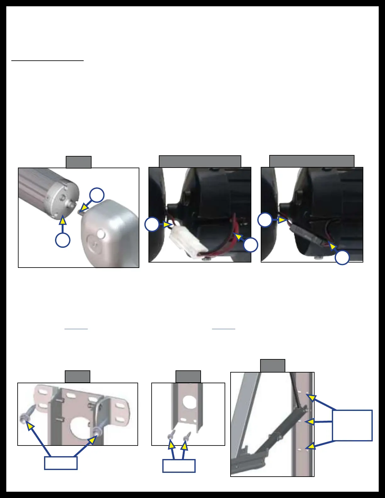
1. Insert drive head pin (Fig. 1A) into end cap (Fig. 1B). Align holes and secure with waxed screw. Insert
screw fully, but do not over-tighten. Repeat process for idler head at other end.
NOTE: Be sure to align LED light wires (Fig. 2A or 3A) coming from idler head with the LED light on roll tube
(Fig. 2B or 3B).
A
B
A
B
Resources Required
• Three people
• Cordless or Electric Drill or Screw Gun
• Appropriate Bits
• Rivet Gun
2. Connect the plug from the idler head (Fig. 2A or 3A) to the plug from the LED light (Fig. 2B or 3B) on
the roll tube.
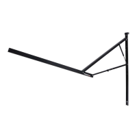
3. Station a person at each end of the awning assembly to hold the support arms. A third person will line
up the polycord with the previously-installed awning rail. Slide the polycord to desired position.
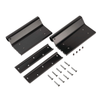
4. Set the awning assembly to the desired height and attach it to the side of the unit with two #14 x 1
½
”
screws (286576) at the top (Fig. 4) and two #14 x 1
½
” (286576) screws at the bottom (Fig. 5).
NOTE: Make sure the awning assembly is square on the unit prior to mounting the bottom 2 screws.
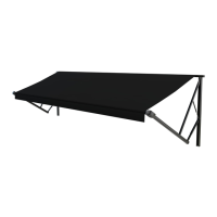
5. Extend the awning half way out by connecting the power and ground wires of the awning to a 12-18V
battery.
Fig. 1
Fig. 2 - Old Connection
286576
286576
Possible
Fastener
Locations
Fig. 3 - New Connection
Fig. 4
Fig. 5
Fig. 6
B
A