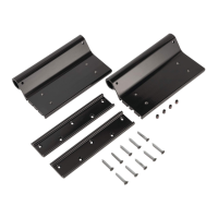
6. Secure the middle of the wall mounting channel with two #14 x 1
½
” screws (286576) at any of the
three locations shown (Fig. 6).
7. Repeat this process for the other side of awning assembly.
NOTE: Four rivets with
⁄
" grip range can be used in place of the two middle and two lower screws on
laminated walls.
8. Take the LED power wire that is already fed through the idler leg and connect to the desired power
wire from the unit.
NOTE: Be sure the black wire is connected to a ground and the red wire is connected to a 3 amp max fuse
and then a power source from the unit.
9. Seal all wall penetrations to protect against water intrusion.
NOTE: All screws supporting the awning assembly must have a backer within the structure of the wall of
the unit.
NOTE: Solera® awnings under 21' in length DO NOT require the use of a cradle.
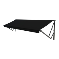
Securing the Fabric
1. Roll the awning in and out several times to ensure that the fabric is square on the roll tube.
2. Secure the fabric in the awning rail 1" inside the edge of the fabric on both ends using a #6 x 1/2” hex
head screw. Install the screw down through the awning rail into the fabric and the polycord.
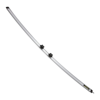
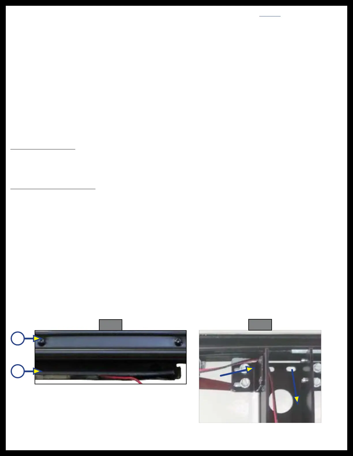
LED Light Rail Installation
NOTE: Solera® Power Awning must be installed prior to LED Light Rail installation.
1. Mount the LED light rail track (Fig. 7B) directly below the awning rail (Fig. 7A) and secure to the side of
the unit.
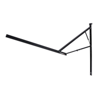
2. Route the light wire over the top of the awning mount leg and run the light wire down through the leg
in the same manner as the motor wire (Fig. 8).
3. Cut wire to desired length and connect to the unit wiring, making sure to connect the red wire on the
light side to the power wire on the unit side.
NOTE: The LED light rail must be wired through a 3 amp (maximum) fused circuit.
4. Connect the black wire on the light to the ground on the unit side.
5. Make sure to seal the light track where it is screwed to the wall and where the light wire connects to
the unit wire.
6. Turn the light on to confirm it illuminates.
Fig. 7
Fig. 8
A
B