SOLERA
®
POWER AWNING INSTALLATION INSTRUCTIONS
TI-144
AWNINGS
Prior To Installation
NOTE: All screws supporting the awning assembly MUST have a backer within the structure of the wall of
the coach.
Resources Required
• Three people
• Cordless or Electric Drill or Screw Gun
• #2 Square Screwdriver Bit
• ⁄" Nut Driver Bit and/or Rivet Gun
Installation
1. Insert drive head pin into end cap (Fig. 1). Align holes and secure with waxed screw. Insert waxed screw fully,
but do not over-tighten. Repeat process for idler head at other end.
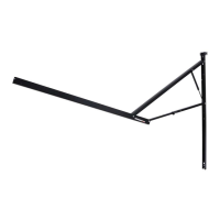
2. With two people holding the support arms, one at either end of the awning assembly, a third person needs
to line up the polycord on the fabric with the awning rail that has been installed on the coach. Slide the fabric
cord the length of the awning rail.
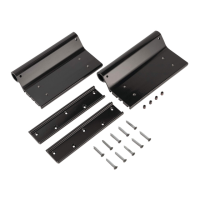
3. Set the awning assembly to the desired height and attach it to the side of the coach with two (2) #14 x 1 ½”
screws (286576) at the top (Fig. 2) and two (2) #14 x 1 ½” (286576) screws at the bottom (Fig. 3).
NOTE: Make sure the awning assembly is square on the unit prior to mounting the bottom 2 screws.
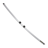
4. Connect the assembly to a power source, cut the tie straps, and run the awning half way out. Remove wire
cover to expose the mounting holes. Secure the middle of the wall mounting channel with two (2) #14 x 1
½” screws (286576) at any of the three locations shown (Fig. 4). Repeat this process for other side of awning
assembly.
NOTE: Four rivets with ⁄" grip range can be used in place of the two middle and two lower screws on laminated
walls.
5. Connect switch to power source.
Fig. 1
Fig. 2
Fig. 3
Fig. 4
286576
286576
Possible
screw / rivet
locations