Do you have a question about the Loadrite Sprint and is the answer not in the manual?
Describes the function and meaning of indicator lights on the LCD screen.
Explains the special functions of the keypad buttons beyond numeric entry.
Explains the system's ability to accumulate weight, referred to as Total mode.
Details the two independent totals stored by the Loadrite for accumulated weights.
Provides essential conditions for achieving accurate weight measurements with the system.
Outlines the step-by-step procedure for weighing a load.
Details the automatic power-up sequence when the loading machine ignition is switched on.
Explains how to put the Loadrite into standby mode and how to restart it.
Describes the screen displayed after extended shutdown and the warm-up procedure.
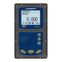
Explains the status displayed when the Loadrite is ready to weigh.
Illustrates the process of lifting and weighing a load using the system.
Describes an optional mode where the display is always live without a trigger.
Details the procedure for adding the weight of a lifted load to the totals.
Explains how to reset the short total to zero for a new operation.
Describes the basic importance and process of zeroing the Loadrite.
Explains automatic reminders to perform a zero check and how to clear them.
Details a specific zeroing procedure for when Auto-Add is active.
Details the process of adding a lifted weight to the totals.
Explains the optional automatic addition of loads as they are lifted.
Describes how to remove a previously added load from the totals.
Provides a detailed explanation of the zeroing process and error handling.
Explains how to re-display and potentially re-apply the last recorded load.
Details how to access and view the accumulated long total.
Explains how to clear both the short and long totals from the system.
Accesses installation functions requiring a security code.
Allows changing the language setting of the Loadrite.
Enables changing the internal clock (date/time) setting.
Allows selection of the correct scale for different implements.
Option to view the long total of the current product.
Setting to enable or disable the auto add function.
Displays a bar graph showing the rotary trigger's current position.
Examines properties and status of the connected data logger module.
Displays the current usage of the internal logging buffer.
Allows deletion of data in the internal logging buffer.
Tests various internal memory and devices of the Loadrite.
Enables PC communication for programming product names and data lists.
Details how weight data can be printed when a Loadrite printer is connected.
Explains how lifting speed affects accuracy and recommends keeping engine revs constant.
Emphasizes lifting at a steady speed past the trigger point for accuracy.
Discusses how machine bounce affects accuracy and how to minimize it.
Explains how the load's center of gravity affects hydraulic pressure and measurement.
Indicates a problem with the power supply voltage to the Loadrite.
Signals a fault in the pressure transducer or its connecting cable.
Detects a fault in the trigger mechanism or its cable.
Reminds the operator to perform a zero check, indicating a potential zero error.
Indicates that the detected lift pressure was too low.
Occurs when the data logger module is full or absent, causing data loss.
Reports an error during writing to the data logger module.
Indicates the data logger module has reached its storage capacity.
Means the interlock was not closed during lifting, preventing weight addition.
Signals that the lifted weight exceeds the system's full scale capacity.
Indicates the printing function was disabled during installation.
Reports a fault with the connected printer, such as being offline.
Indicates the recall function is not available, likely due to Static Weigh mode.
Occurs when the zero function is attempted on a weight exceeding scale limits.
Message displayed after extended shutdown, requiring a warm-up lift.
Lists the typical vehicles and uses for the Loadrite system.
Notes the minimal delay due to weighing during a normal lift.
Details the supply voltage and current requirements for the indicator and printer.
Lists the types of signal inputs and outputs for the system.
Describes the type of display used by the Loadrite system.
Specifies the number of keys and their backlight status.
Details the built-in clock's compliance and format.
Provides physical specifications like protection ratings and weight.
Lists optional features like printer, data logger, and remote button.
Lists the pin connections for the transducer.
Details the pin connections for power supply and control signals.
Lists the pin connections for printer communication.
Provides instructions and a flow chart for setting the system's time and date.
Details how to edit and confirm the time setting on the display.
Explains how to edit and confirm the date setting.
Describes how to edit and confirm the year setting.
Details how to set the 24-hour format for the time display.
Explains how to verify the calibration adjustment.
Provides important reminders for accurate calibration.