50
THIS MANUAL IS PROPRIETY OF ECOWIND by LOMBARDINI - ALL FORMS OF REPRODUCTION, PARTIAL OR OTHERWISE, IS STRICTLY PROHIBITED
G
B
Fig. 93
Fig. 92
Fig. 94
Fig. 95
down oor cab
F
ASSEMBLY AND INSTALLATION - 3
Step Description
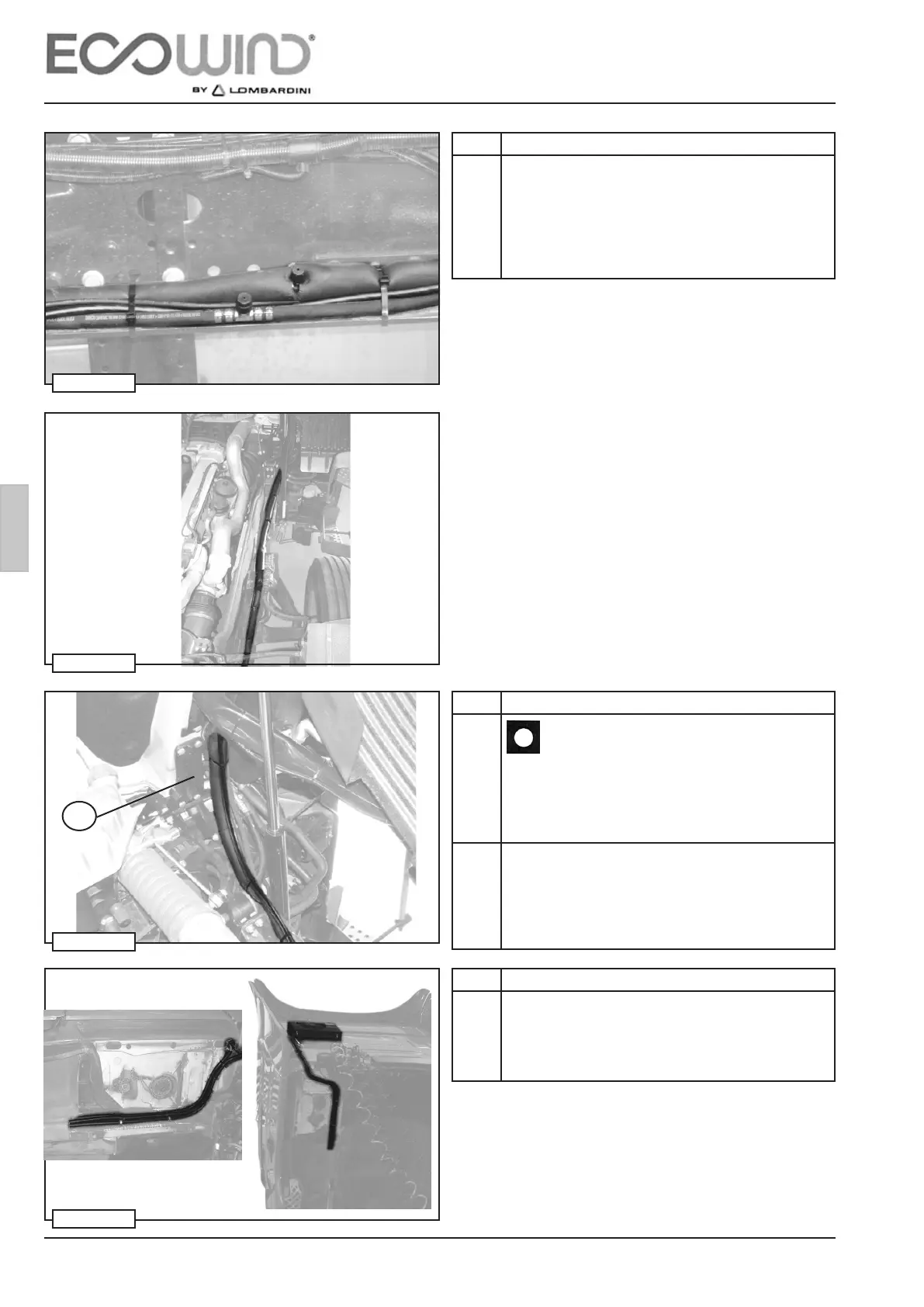
2 After fastening the Power Unit, overturn the vehicle
cabin and fasten the gas pipes and the electrical
cables (regardless of the position in which the con-
densing unit has been installed) to the vehicle frame
using steel, rubber and plastic clamps and a range
of nuts and bolts supplied with the system, as far as
the rotation fulcrum point F of the cabin, g 92-93-94.
Step Description
5 When the cab rotation fulcrum point F has been rea-
ched (g. 95), x the tube bundle to the the cab and
down oor cab (g. 95), boring holes (Ø 3,5 mm) and
using steel/rubber clamps along with self-threading
screws supplied with the system.
Step Description
3
WARNING
While positioning, remember to protect the ends
of the GAS G6 / G8 / G10 pipes with adhesive tape,
in order to prevent entry of impurities or residues
dangerous to the passage of the coolant.
4 When possible, use the existing original tube bundles
(g. 95), in order to use only the plastic clamps sup-
plied, to prevent perforation.
When this method is used, it is necessary to determine
the best passage taking the pipes and electrical cables
to the peripherals.