EasyManua.ls Logo

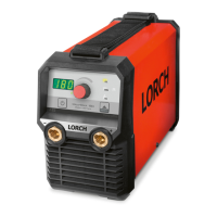
LORCH MicorStick 180 ControlPro User Manual

LORCH MicorStick 180 ControlPro
202 pages
Go to English
To Next Page IconTo Next Page
Page #1 background imageLoading...
Page #1 background image
Lorch Schweißtechnik GmbH Im Anwänder 24 - 26 71549 Auenwald Germany
Tel. +49 7191 503-0 Fax +49 7191 503-199 info@lorch.eu www.lorch.eu

Table of Contents

Questions and Answers:

LORCH MicorStick 180 ControlPro Specifications

General IconGeneral
BrandLORCH
ModelMicorStick 180 ControlPro
CategoryInverter
LanguageEnglish

Summary

Machine Elements

Explanation of Symbols

Symbols in Operation Manual

Explains the meaning of symbols used within the operation manual for safety and guidance.

Symbols on the Machine

Details the meaning of symbols found directly on the welding machine itself.

General Safety Precautions

Accident Prevention Inspection (UVV)

Ambient Conditions

General Use Regulations

Machine Protection and Switch-on Duration

Electromagnetic Compatibility (EMC)

Mains Connection Requirements

Noise Emission Levels

Setup and Transport

Brief Operating Instructions

Before Start-up Procedures

Fastening the Transportation Belt

Details how to properly attach the transportation belt to the welding machine.

Connecting the Ground Cable

Explains the correct procedure for connecting the ground cable for safe and effective welding.

Connecting the Power Supply

Guides the user on connecting the machine to the mains power supply, including safety warnings.

Power Source Operation Modes

Mains Extension Cables

Provides guidance on selecting and using mains extension cables safely and effectively.

Electrode Welding Process

Details the setup and connection for performing electrode welding (MMA).

TIG Welding Process

Describes the setup and connection requirements for TIG welding.

Control Panel Overview

Fault LED Status

Describes the behavior of the fault LED and its meaning for system status.

Remote Control LED Indicator

Indicates the status of the remote control connection and its operation.

VRD LED Indicator

Explains the VRD LED's function indicating voltage reduction status.

Main Control Knob

Details the operation of the main control knob for setting current and navigating menus.

Process Selection LEDs

Explains the LEDs that indicate the selected welding process (CEL, MMA, TIG).

Pulsing LED Status

Shows how the pulsing function is indicated on the control panel.

Welding Process Operations

Electrode Welding Procedure

Details the steps for setting up and executing electrode welding, including arc ignition.

TIG Welding Procedure

Secondary Parameters Configuration

Machine Configuration Menu

Special Functions and Settings

Master Reset Procedure

Explains how to perform a master reset, returning all settings to default values.

System Messages and Errors

Error Messages and Solutions

Lists common error codes, their causes, and recommended actions for troubleshooting.

Troubleshooting Guide

Technical Data Summary

Maintenance and Repair Guidelines

Regular Machine Checks

Lists essential points to check regularly for damage to ensure proper machine operation.

Disposal and Recycling

Service and Technical Documentation

Declaration of Conformity