Explanation of symbols
- 24 - 07.19909.4119.9-02
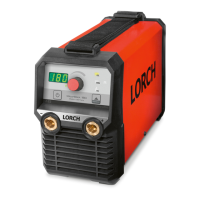
1 Machine elements
I
1 Carrying belt
2 Display/User Interface
3 Positive terminal socket
4 Negative terminal socket
5 Air intake
6 Power cable/battery cable with device
coupling (optional)
7 Connection socket for remote control
(MicorStick 180 RC)
Danger of death through electrocu-
tion!
See chapter “13.3 Connecting the
power supply” on Page 28.
Some depicted or described accesso-
ries are not included in the scope of
delivery. Subject to change.
2 Explanation of symbols
2.1 Meaning of the symbols in the
operation manual
Danger to life and limb!
If the danger warnings are disregarded,
this can cause slight or severe injuries
or even death.
Danger of property damage!
Disregarding danger warnings can
cause damage to workpieces, tools,
and equipment.
General note!
Indicates useful information about the
product and equipment.
Bullet points:
Work instruction.
Designates operations that have to be carried
out.
Result.
Designates the result of the operation(s).
Note
Designates an explanation / information
2.2 Meaning of the symbols on the
machine
Danger!
Read the user information in the opera-
tion manual.
Disconnect the mains plug!
Pull out the mains plug before opening
the housing.