Pc-Boards
- 33 -02.20 909.2710.1-06
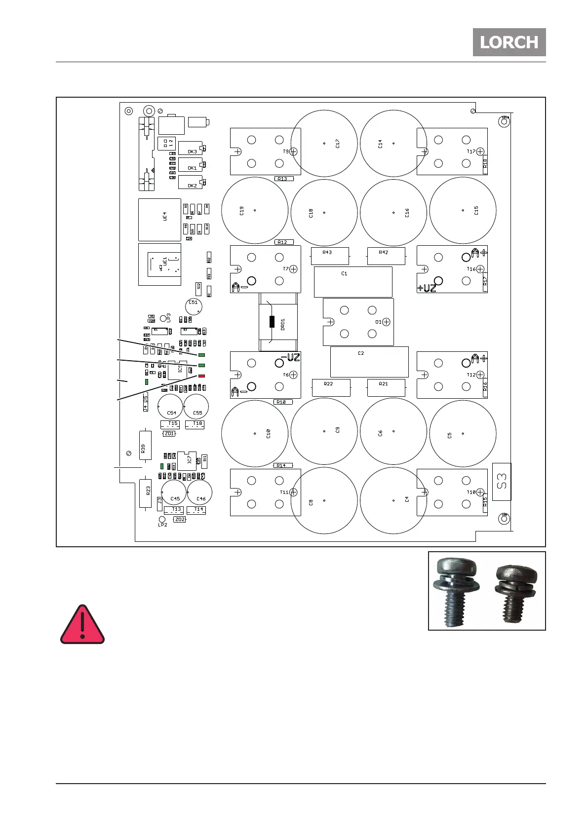
Picture pc-board DCDR2x
X3
X2
X1
S1
LED6
LED4
LED1
LED2
LED5
T
T T
T
T
TT
T
D
L
L
L L
L
L
LED6
UZmin
LED4
UZmax
LED1
ovr cur
LED2
drv low
LED5
drv hi
Fig. 21: Pc-board DCDR2x
T=MOSFET (power transistor)
D=diode
!!! CAUTION !!!
at all positions where cables are attached, the longer screws are
used (A+ A- +UZ -UZ).
The rest of the ISOTOP screws are the short ones. All screws need to be tightened with a
torque of 2.2Nm.
If a MOSFET should fail, all MOSFETs have to be replaced including the DCDR. This is necessary because
all MOSFETs must have the same switching times (all MOSFETs out of one production batch). In the case
of a defective MOSFET, it is very likely that the drive circuit on the DCDR module is also damaged or pre-
damaged. Therefore, in this case also the pc-board DCDR has to be exchanged.