page 25
Pc-board DK-KSDC / DK-KSDCD / DK-KSDCN
The pc-board DK-KSDC is an additional support for the HF ignition.
Functions
- electronic short-circuit switch for HF ignition support
LEDs
normal
LED state designation
1 (green) on supply voltage +15V DC ok
malfunction
LED state cause
1 (green) o supply voltage +15V DC of pc-board DK-MAPRO is missing
Measuring points
designation measuring point result
secondary output voltage
(in stick electrode mode)
X5
X7
+
GND
about 58V DC
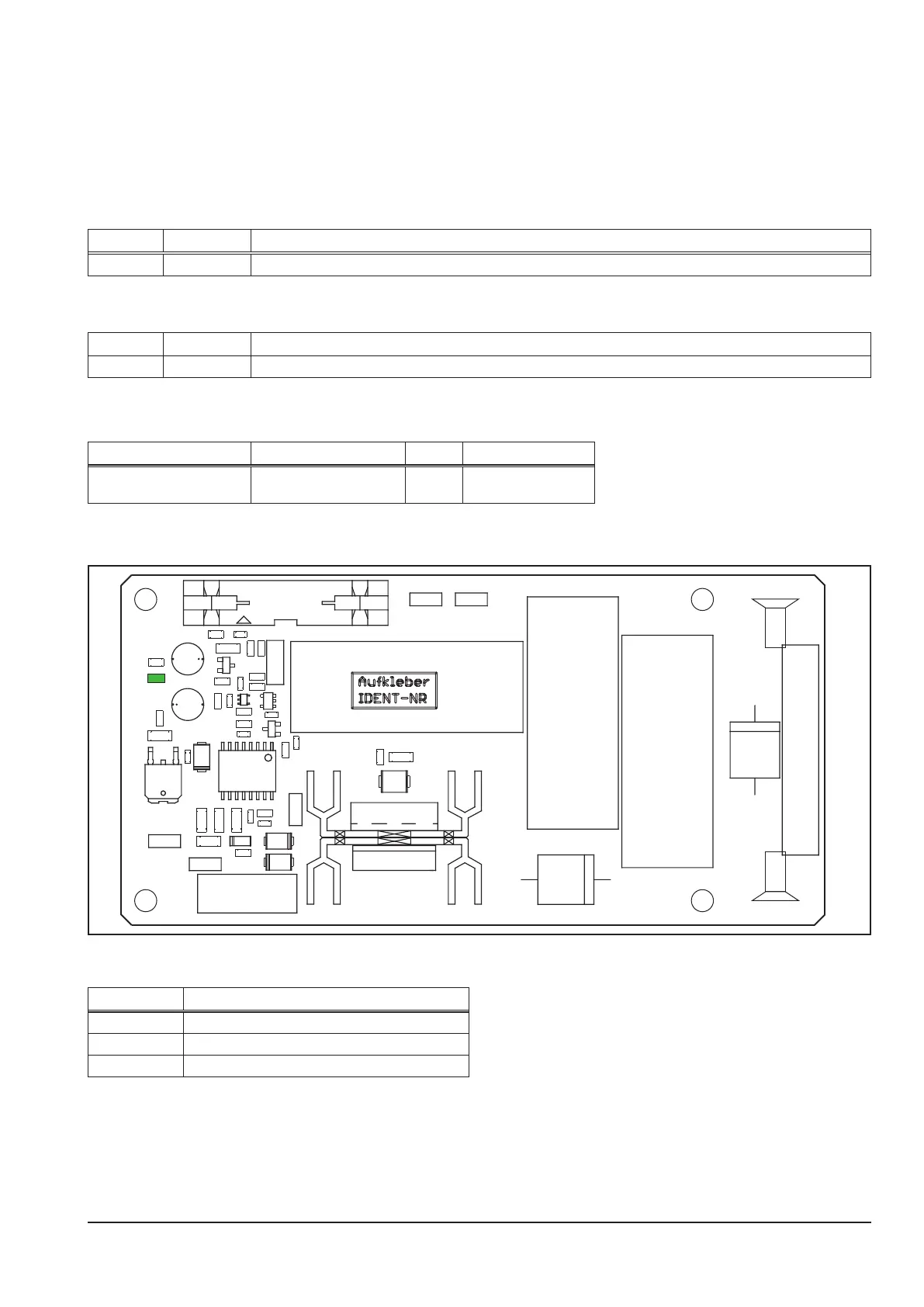
Picture pc-board DK-KSDCN
UG+
UG-
+ red
- blue
X1
+15V
C1
C2
C3
C4
C5
C6
C7
C8
C9
C10
C11
C12
C13
C14
C15
C16
C17
D1
D2
D5
D6
D7
D8
D9
DRO1
DRO2
IC1
123
IC2
IC3
KK1
KK2
LED1
OK1
R1
R2
R3
R4
R5
R6
R7
R8
R9
R10
R11
R12
R13
R14
R15
R16
R17
R18
R19
R20
R21 R22
R23
R36
SI1
T1
T2
ZD2
ZD3
X5
X7
Overview connectors pc-board DK-KSDCN
connector designation
X1 interface to pc-board DK-MAPRO
X5 connector to output socket (+)
X7 connector to output socket (-)