page 39
Remote control interface
The remote control interface is for connecting a hand or foot remote control. It is also possible to use the interface
for a small automation application.
In case of “inpermissible“ short circuits between the connector pins of the interface, the machine will stop and
displays E11 (remote control conn.).
If the start contact is already closed when the machine is switched on, the machine displays also E11.
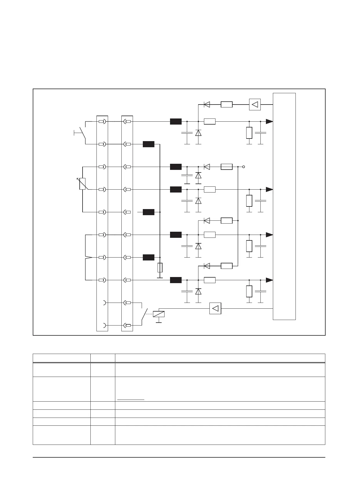
Schematic
1
2
3
4
5
14 pin AMP
Master
6
7
8
9
10
+15V
10k Ω
1
2
3
4
5
X13
6
7
8
9
10
remote
start
external
2-stroke
arc established
I > 0
Signal overview
Signal pin designation
weld start 1 and 2 as soon as pin 1 and 2 are connected, the machine starts (same function as pressing the torch
trigger switch)
weld energy 4
analog input for setting the weld energy (e.g. with an potentiometer)
0V = minimum setting of the actual welding program
15V = maximum setting of the actual welding program
! CAUTION ! this analog input is only valid if the identication “external“ on pin 6 and 7 is active
identication “external“ 6 as soon as pin 6 is connected to pin 7, the analog input on pin 4 is valid
ground 7 gnd for the identication signals on pins 6 and 8
identication “2 stroke“ 8 as soon as pin 8 is connected to pin 7, the machine operates in 2-stroke mode at “weld start“
arc established 9 and 10 potential free relay contact (closing contact)
as soon as welding current is owing, this relay contact is connecting pin 9 to 10
maximum contact load: 1A