page 28
Schematic DK-HFDC
HV
1000V
+15V
DK-HFDC
X1 / 1
X1 / 4
X1 / 8
X1 / 3
X1 / 9
X1 / 6
X1 / 5
X1 / 2
DK-MAPRO
X11 / 1
X11 / 4
X11 / 8
X11 / 3
X11 / 9
X11 / 6
X11 / 5
X11 / 2
+24V
CPLD
X1 / 10X11 / 10
Trig. +
Trig. -
G-PWM
HF
X3 / 2
X3 / 1
load ig.
Power Unit
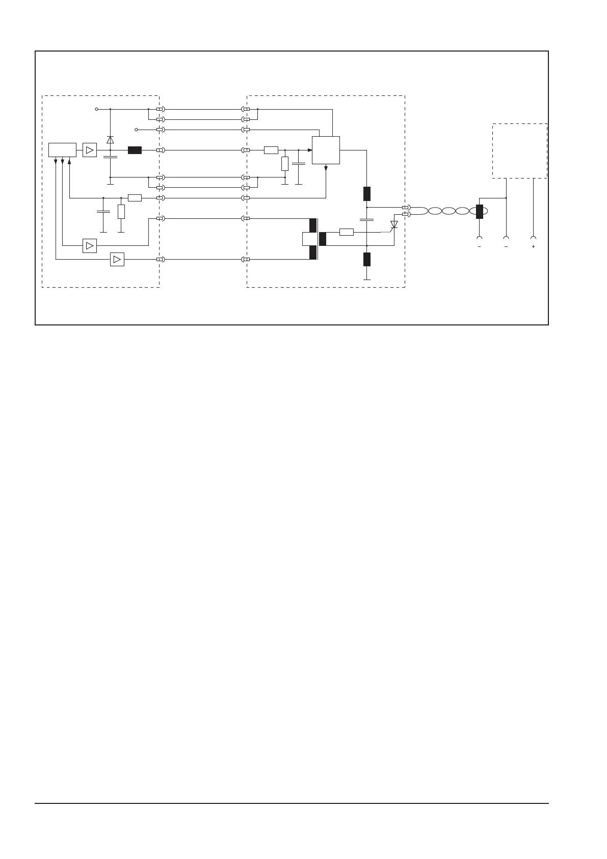
Ignition Sequence
The pc-board DK-MAPRO activates +24V DC on pin 8. This causes the pc-board DK-HFDC to charge the ignition
capacitor up to 1000V. The charging process is monitored by the CPLD. As soon as the 1000V are reached, the
ignition impulse is triggered with a thyristor (trigger impulse via pins 5 and 6).
If the CPLD can not read the PWM signals of the ignition board, the complete process is stopped and the error
meassage E19 (error ignition device) is shown in the display of the machine.
Possible reasons could be:
- the 24V at pin 8 are missing
- loose contact of the at ribbon cable between MAPRO board and HFDC board
- faulty HFDC board