L-STAT User Manual 24 LOYTEC
Version 1.0 LOYTEC electronics GmbH
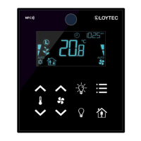
ir_remote_control_
command
This register provides the button_code and remote_id of a valid command received via the
infrared receiver. See Chapter 5 for detailed information.
Whenever a command was received the ir_remote_control_command register is
updated and the IRC flag of the short_pressed register at address 1 is set (see Table 7
on Page 22).
Table 9: IR Remote Control Command
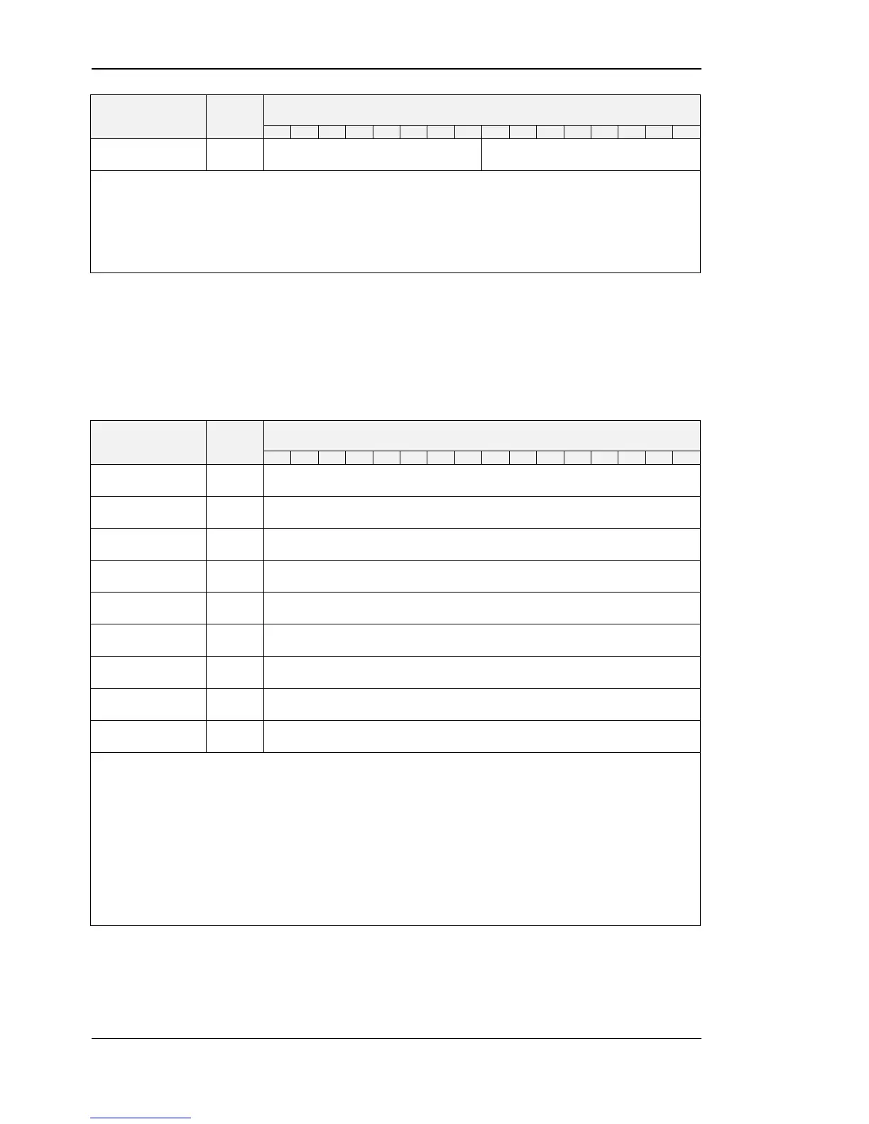
The following Table gives an overview of the internal sensor values. These registers can be
read over Modbus and can be used as source for a display value if configured. As described
in Section 2.2.2 on Page 15 there are up to 16 display values used to visualize data.
Each display value has two 16 bit configuration registers to specify the values displayed.
Display values (register address 64 to 79) are read- and writable over Modbus.
amount CO
2
(applies only to LSTAT-802-Gx-Lx)
A sensor value can be used as source for a display value. Therefor the DSSA or DSEU
bit as well as the semantic meaning at the corresponding display value configuration at
address 256 to 286 has to be set (see Table 28 on Page 39). If the DSSA or DSEU bit
is set this specifies that a sensor value is used instead of a display value. The semantic
meaning specifies which sensor value is used as source for displaying. For an overview
on this topic please see Figure 6 on Page 21.
Sensor_value_0, sensor_value_1 and sensor_value_3 are 16 Bit signed values. All
other sensor values are defined as 16 Bit unsigned since there are no negative values to
expect. The values are scaled as described in Table 39 at Page 51.