L-STAT User Manual 41 LOYTEC
Version 1.0 LOYTEC electronics GmbH
These registers hold the configuration for the 16 set point.
For both, unit_lstat and unit_modbus the following values are possible:
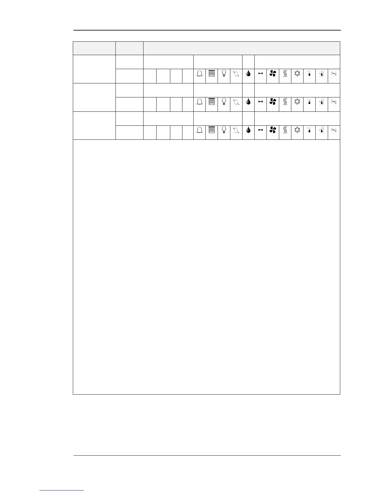
Bits 0-11 of the higher address of each configuration register indicate the symbols that are
displayed along with the corresponding display value.
These two bits define if the set point is editable for the end user and/or the system
administrator. The following states are valid:
0 – defines that the set point is not editable
1 – defines that the set point is editable
Visible for system administrator
These two bits define if the set point is visible for the end user and/or the system administrator.
If set to ‘1’ the set point will be visible.
See Table 31 on Page 43 for example configurations of display values or set points.
is used to provide information about the semantic meaning of the set
point. For further information please see Table 30 on Page 42.
if set to ‘1’ the the corresponding set point is pincode protected
and can only be changed in EDIT-mode if the correct pincode has
been entered before.
defines a unit with which the corresponding set point appears on
the LCD
defines a unit that the corresponding set point register appears on
Modbus
display source for end user
diplay source for system administrator
Table 29: Set Point Configuration