Appendix 3 Control and Monitoring Specific Inverter Data
Appendix 3-4
3.3 Monitoring (Inverter Î PLC Option)
(1) Operation Status Monitoring of iS7 Inverter
Special D register of PLC▶ option card for inverter operation status monitoring
Special D
Register
Function Detailed Description
BIT0
BIT1
BIT2
BIT3
0: Stop
1: Forward operation
2: Reverse operation
3: DC operation (or 0 speed control)
BIT4
BIT5
BIT6
BIT7
1: During speed searching
2: Accelerating
3: Constant speed
4: Decelerating
5: Deceleration to stop
6: During H/W OC restraint
7: During S/W OC restraint
8: Dwell operating
BIT8
BIT9
BIT10
BIT11
Reserved
BIT8
BIT9
BIT10
D4470
Inverter
Operation Status
BIT11
0: Normal Status
4: Warning Status
8: Fault Status
Exemplary program ▶
1) Set up iS7 inverter parameters as follows.
Code Function Name Set Value
DRV01 Cmd Frequency 12.00 Hz
DRV06 Cmd Source Keypad
DRV07 Freq Ref Src Keypad-1
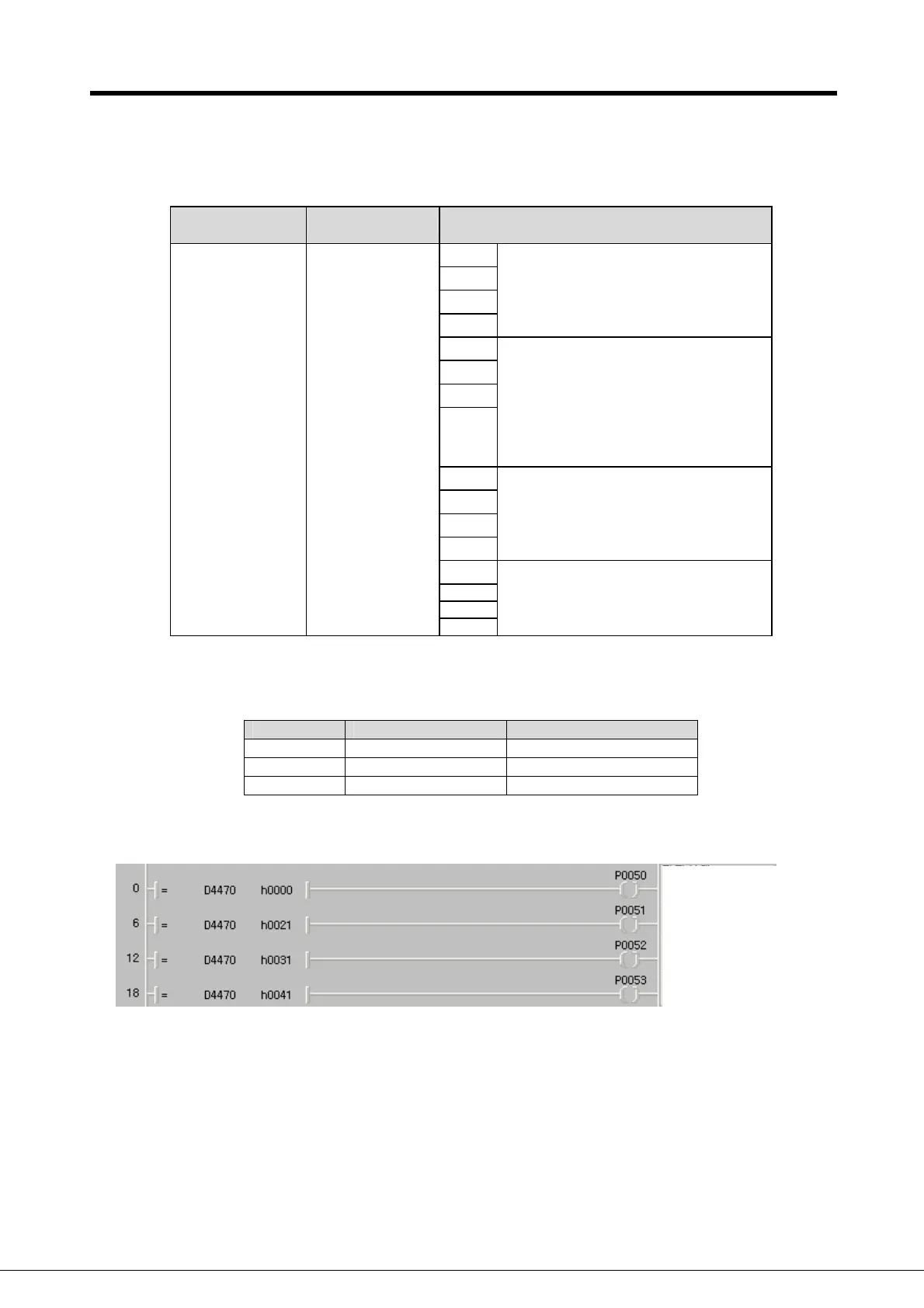
2) Run the KGLWIN and make out following program.
Stopped
Forward Accel.
Forward Constant
Speed.
Forward Decel.
 Loading...