Chapter 7 Exclusive Functions for iS7 Inverter Control/Monitoring
7-20
▶ Application and exemplary program
1) Set up inverter parameters as follows. Especially, enter 0311Hex which is the address of the
inverter’s current output frequency (app. 4-1, page 4, Appendix) in the APO76 (PLC Rd Data1).
Code Function Name Set Value Remark
DRV01 Cmd Frequency 29.00 Hz -
DRV06 Cmd Source Keypad -
DRV07 Freq Ref Src Keypad-1 -
APO76 PLC Rd Data1 0311 Hex -
2) The APO76 (PLC Rd Data1) corresponds by 1:1 with the PLC option’s special register D4474.
Therefore, the value in the D4474 is the data (current output frequency of the inverter) stored in
0311Hex which is the address of the inverter output frequency registered in the APO76 (PLC Rd
Data1).
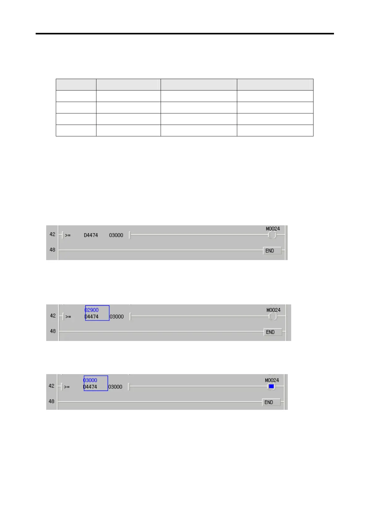
3) For an example with the ladder program below, PLC option can monitor the current output frequency
of the inverter.
4) Press FWD on the digital loader of he inverter for forward operation up to 29.00Hz.
5) The value 2900 is inputted into the D4474 as shown below.
6) Set the DRV01 (Cmd Frequency) to 30.00Hz. Now, the D4474 is changed to 03000 and the M0024
relay is turned ON.
 Loading...