2-2 Detailed Host Adapter Installation
Version 2.3 Copyright © 2002–2004, 2006 by LSI Logic Corporation. All rights reserved.
Step 3. Be sure to touch a grounded metal surface to discharge static
electricity before removing the host adapter from its package.
Caution:
You must touch a grounded metal surface before handling
the host adapter because static charges on your body can
damage electronic components. Handle plug-in boards by
the edge; do not touch board components or gold
connector contacts. LSI recommends that you use a static
ground strap.
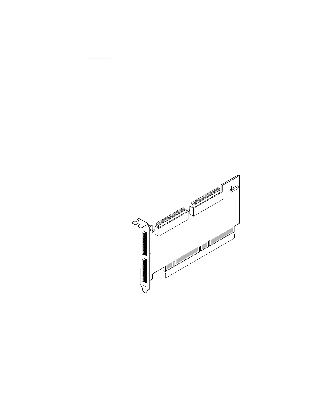
Step 4. Remove your Ultra320 SCSI host adapter from its packaging
and verify that it is not damaged.
Figure 2.1 illustrates the LSI22320 series host adapter and
Figure 2.2 illustrates the LSI22320IE and LSI22320SE host
adapters.
Figure 2.1 Hardware Connections for the Host Adapter
Step 5. Find an unused PCI/PCI-X/PCI Express slot.
Note:
You can insert a 64-bit host adapter into a 32-bit slot if no
64-bit slots are available. However, this limits the data
transmission rate to 32-bit transfers.
Channel A
68-Pin Internal
High Density (HD)
SCSI Interface
Channel B
68-Pin Internal
HD SCSI Interface
68-Pin External
Very High Density Cable
Channel A & B
Busy LED
J5 Connector
Channel B
68-Pin External
Channel A
J4 Connector
J6 Connector
J1 Card Connector
Universal Type Board Edge
PCI/PCI-X/PCI Express Bus to Mainboard
SCSI J3 Connector
Interconnect (VHDCI)
VHDCI SCSI
J2 Connector
 Loading...