S100 PROFInet Option Manual
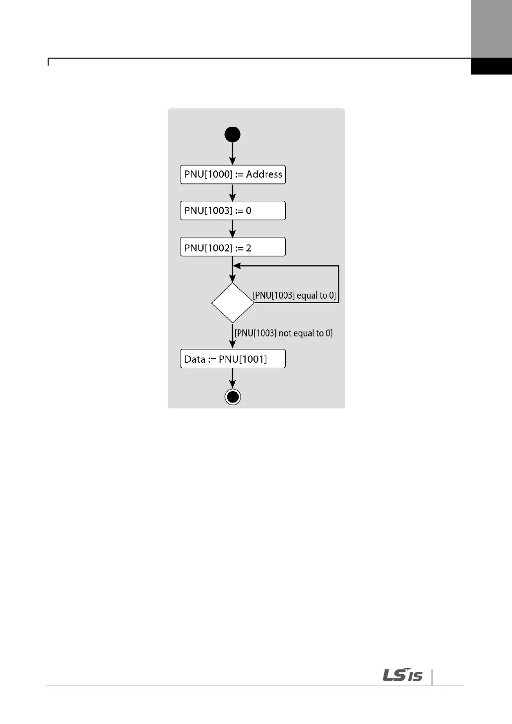
The following diagram explains the parameter reading procedure.
1 Inverter communication address is assigned to PNU [1000].
2 PNU [1003] is set to 0.
3 When PNU [1002] is set to 2, the S100 PROFInet communication module
references PNU [1000] and reads the data saved in the inverter’s internal address
pointed by it.
4 After reading the inverter’s internal parameters, the S100 PROFInet
communication module saves the result to PNU [1003]. If the reading procedure is
successful, it saves the read data to to PNU[1001].
5 PNU [1003] is used to verify successful completion of reading procedure. If the
reading procedure is successful, the PLC reads the data saved at PNU[1001].

 Loading...


