7-3
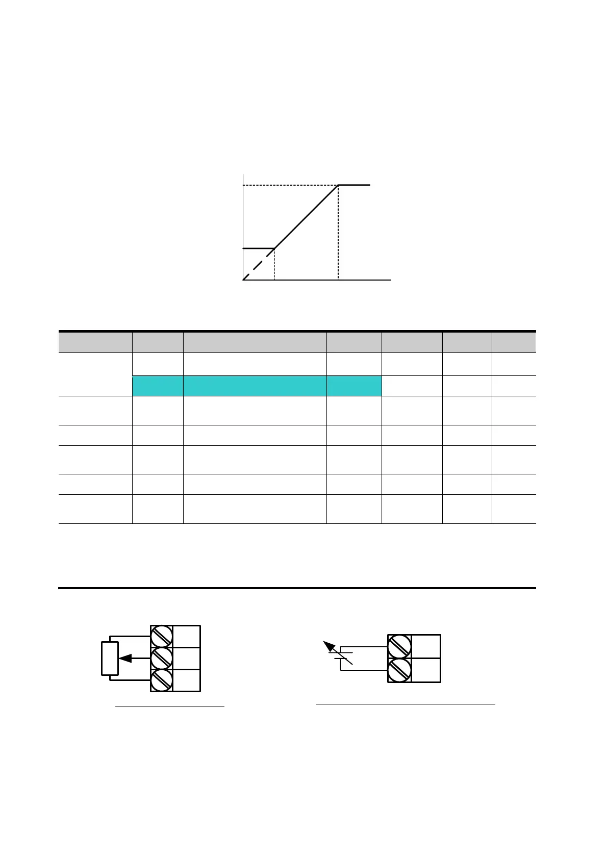
I6 ~ I10: Setting input range and corresponding frequency to 0 ~ +10V V1 input voltage
Ex) when minimum (+) input voltage is 2V with corresponding frequency 10Hz and Max
voltage is 8V with run freq.
z Frequency setting via 0 ~ 10 [V] input or Terminal Potentiometer
Group Code Parameter Name Setting Range Initial Unit
Drive group 0.00 [Frequency Command] - 0 ~400 0.00 Hz
Frq [Frequency Mode] 3
0 ~ 8 0
I/O group I 6
[Filter time constant for V1
input]
10 0 ~ 9999 10
I 7
[V1 input Min voltage]
- 0 ~ 10 0 V
I 8
[Frequency corresponding
to I 7]
- 0 ~ 400 0.00 Hz
I 9
[V1 input max voltage]
- 0 ~ 10 10 V
I10
[Frequency corresponding
to I 9]
- 0 ~ 400 60.00 Hz
Select 3 in Frq code of Drive group.
0-10V can be directly applied from an external controller or a potentiometer connected on
terminals VR, V1 and CM.
Wire the terminals as shown below and refer to I 6 ~ I 10.
VR
V1
CM
Wiring of potentiometer
V1
CM
0 ~ 10V input via external controller
Set freq.
V1 input
I 7 I 9
I 8
I 10
2V 8V
10Hz
50Hz
 Loading...


