EasyManua.ls Logo

LSIS XGK-CPUU - Terminator Connections

LSIS XGK-CPUU
205 pages
To Next Page IconTo Next Page
To Previous Page IconTo Previous Page
Loading...
Chapter 2 System Configuration
2 -9
2.3.4 Terminator Connections
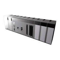
When an expansion base is connected, a terminator must installed for the system reliability on the
expansion connector (OUT) of the last expansion base.
2.3.4.1 Structure
2.3.4.2 Installation Position
Extension cable
Main base
(No. 0)
Expansion base
(No. 1)
Slot No.
01
2
3
5
46 7
CPU
P000
0
~
P000F
P0010
~
P001F
Power
P0020
~
P002F
P0030
~
P003F
P0040
~
P004F
P0050
~
P005F
P0060
~
P006F
P0070
~
P007F
Slot No.
01
2
3
5
46 7
P0080
~
P008F
P0090
~
P009F
CPU
P0100
~
P010F
P0110
~
P011F
P0120
~
P012F
P0130
~
P013F
P0140
~
P014F
P0150
~
P015F
Terminator

Table of Contents