EasyManuals Logo
Home>Lutron Electronics>Control Unit>QS Timeclock

Lutron Electronics QS Timeclock Quick Installation And Operation Guide

Lutron Electronics QS Timeclock
144 pages
To Next Page IconTo Next Page
To Previous Page IconTo Previous Page
Page #75 background imageLoading...
Page #75 background image
Kurzanleitung für Installation und Betrieb der QS-Zeitschaltuhr 3
®
D1 D1 D2 D2
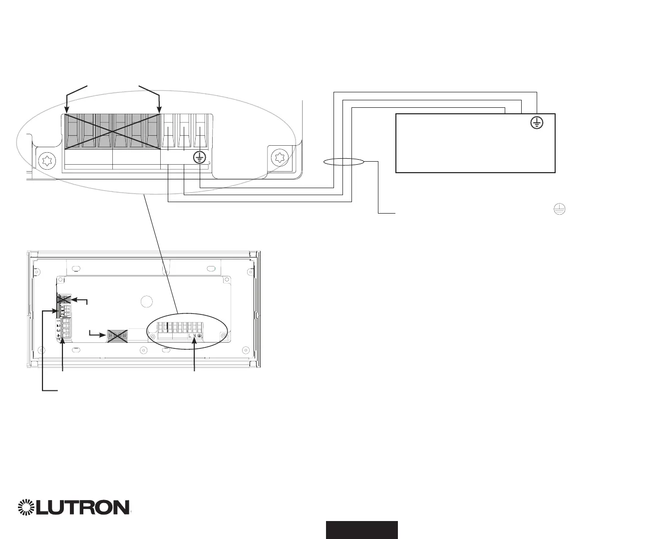
• Die Netzverkabelung vom Verteilerschrank zur QS-Zeitschaltuhr legen.
• Jede Netzspannungsklemme kann eine 4,0-mm² (12 AWG)-Leitung aufnehmen.
Anschluss der Netzleitungen
D1 D1 D2 D2
NICHT
BENUTZT
Rückseite der
QS-Zeitschaltuhr
1234
12
ABC
123456LN
Netzverkabelung (Leitung/Phase)
ist mit L gekennzeichnet.
100–240 V~ nur
Schaltschrank
1234
12
ABC
123456LN
Abschlüsse
QS-Kommunikationslink
Eingängen mit potenzialfreien
Kontakten und 24 V- leistungs
NICHT
BENUTZT
Eingangsleistung
L: Leitung/Phase
N: Neutralleiter
: Erde

Table of Contents

Other manuals for Lutron Electronics QS Timeclock

Questions and Answers:

Question and Answer IconNeed help?

Do you have a question about the Lutron Electronics QS Timeclock and is the answer not in the manual?

Lutron Electronics QS Timeclock Specifications

General IconGeneral
BrandLutron Electronics
ModelQS Timeclock
CategoryControl Unit
LanguageEnglish

Related product manuals