QS Timeclock Installation and Operation Guide 6
• Each IEC PELV/NEC® Class 2 terminal
accepts up to two 18 AWG (1.0 mm²)
wires.
• Connect the terminal 1, 3, and 4
connections to all control units,
wallstations, and control interfaces.
• Total length of control link must not
exceed 2000 ft (610 m).
• Do not allow IEC PELV/NEC® Class 2
wires to contact line/mains wires.
• The QS Timeclock provides 3 PDUs
(Power Draw Units) on the QS Link.
For more information, see Lutron
P/N 369405, “Power Draw Units on the
QS Link” at www.lutron.com
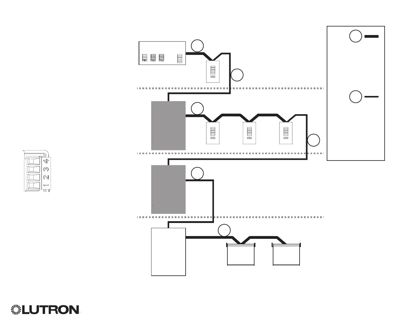
QS Communication Link
Terminal Detail
QS Link Wiring
_
MUX
24 V-
COM
LUTRON
LUTRON LUTRON LUTRON
Energi Savr Node
Sivoia QS
smart
power
panel
Sivoia QS
shade
Sivoia QS
shade
QS Timeclock
Wallstation
Wallstations
Connect all 4
terminals within a
power group:
1: Common
2: 24 V-
3 and 4: Data
Connect only 3
terminals between
power groups:
1: Common
3 and 4: Data
Do not connect
Terminal 2: 24 V-
A
B
A
A
A
B
B
B
Power Group 1
Power Group 2
Power Group 3
Power Group 4
Energi Savr Node
Wiring Example