214251 14 Revision A
%
$
$
$
$
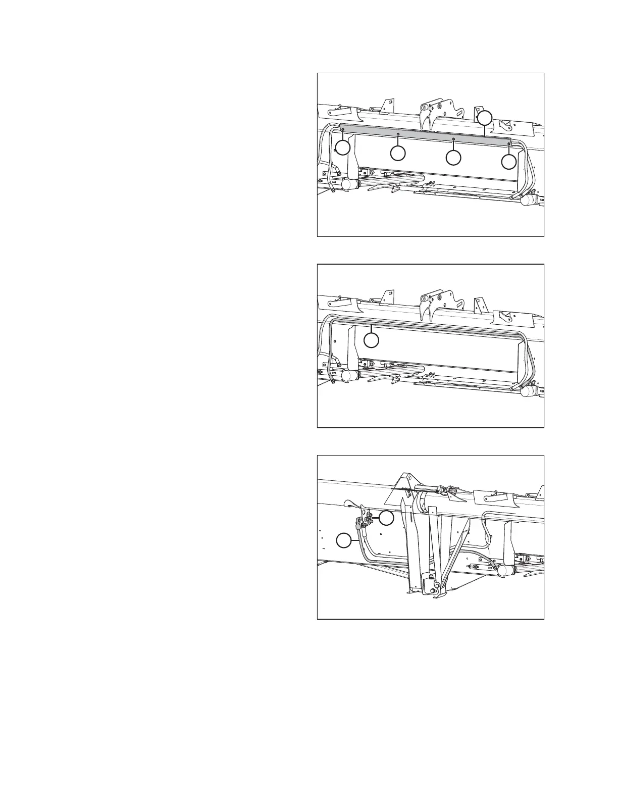
Figure 3.11: Draper Drive Hose Holder
2. Remove four hex head bolts (A) from weld nuts and remove
the draper drive hose holder (B) from header. Retain
hardware (A) and hose holder (B) for later reinstallation.
$
Figure 3.12: Side Draper Interconnect Hose
3. Discard side draper interconnect hose (A) previously
connected to the factory-installed left and right side
draper motors.
$
%
Figure 3.13: Side Draper Pressure Hose
4. Disconnect side draper pressure hose (A) from the coupler
holder (B) at header’s left side. Discard side draper
pressure hose.
NOTE:
Couplers removed from illustration for clarity.
INSTALLATION INSTRUCTIONS