UNLOADING AND ASSEMBLY
Form 169018 38 Revision C
(continued next page)
L2 Cxxx
TO C
LIBR
TE SELECT
L2 Mxxx
HE
DER HE I GHT
L2 Mxxx
HE
DER T I LT
L1 Mxxx
HE
DER FLO
T
L2 Mxxx
EX I T C
L? NO/
ES TO C
LIBR
TE SELECT
L1 Cxxx
DI
GNOST I C MODE?
L2 Mxxx
NO /
ES TR
CTOR SETUP?
L1 Cxxx
I EW ERROR CODES?
L2 Mxxx
NO /
ES ENTER SENSOR SETUP?
L1 Cxxx
IEW TR
CTOR CODES?
L2 Mxxx
NO/
ES
IEW ENGINE CODES?
L1 1
1234.5 HRS 123
L2 E 4 7
SENSOR
OLTS LOW
L1 2
1230.5 HRS 123
L2 E 7 1
LOW H
DR
UL I C OI L
L1 Cxxx
EXIT TR
CTOR CODES?
L2 Mxxx
NO/
ES
L1 Cxxx
I EW ENGI NE CODES?
L2 Mxxx
NO/
ES ENTER SENSOR SETUP?
L1 1
1234.5 HRS 123
L2 449
FUEL PRESSURE H IGH
L1 Cxxx
EX I T ENG I NE CODES?
L2 Mxxx
NO/
ES
L1 Cxxx
EX I T ERROR CODES?
L2 Mxxx
NO/
ES
IEW TR
CTOR CODES?
L1 Cxxx
ENTER SENSOR SETUP?
L2 Mxxx
NO /
ES RE
DSENSOR INPUTS?
L1 Cxxx
KNI FE SPEED SENSOR
L2 Mxxx
EN
BLE / D I S
BLE
L1 Cxxx
REEL SPEED SENSOR
L2 Mxxx
EN
BLE / D I S
BLE
L1 Cxxx
HE
DER HT SENSOR
L2 Mxxx
EN
BLE / D I S
BLE
L1 Cxxx
HE
DER T I LT SENSOR
L2 Mxxx
EN
BLE / D I S
BLE
L1 Cxxx
HE
DER FLO
TSENSOR
L2 Mxxx
EN
BLE / D I S
BLE
L1 Cxxx
O
ERLO
D PRESSURE
L2 Mxxx
EN
BLE / D I S
BLE
L1 Cxxx
H
D OIL TEMP SENSOR
L2 Mxxx
EN
BLE / D I S
BLE
L1 Cxxx
EX I T SENSOR SETUP?
L2 Mxxx
NO/
ES KNI FE SPEED SENSOR
L1 Cxxx
RE
D SENSOR INPUTS?
L2 Mxxx
NO /
ES
CT I
TE FUNCT I ONS?
L1 Cxxx
SENSOR I NPUT
L2 Mxxx
HDR HE I GHT 3 . 59
L1 Cxxx
SENSOR I NPUT
L2 Mxxx
HDR
NGLE 1 . 8 4
L1 Cxxx
SENSOR I NPUT
L2 Mxxx
2.45
FLO
T2.84
L1 Cxxx
SENSOR I NPUT
L2 Mxxx
KNI FE SPEED 123 HZ
L1 Cxxx
SENSOR I NPUT
L2 Mxxx
REEL SPEED 123 HZ
L1 Cxxx
SENSOR I NPUT
L2 Mxxx
WHEEL SPEED 123 HZ
L1 Cxxx
SENSOR I NPUT
L2 Mxxx
H
D OIL TEMP 1.00
L1 Cxxx
EX I T RE
DSENSORS?
L2 Mxxx
NO/
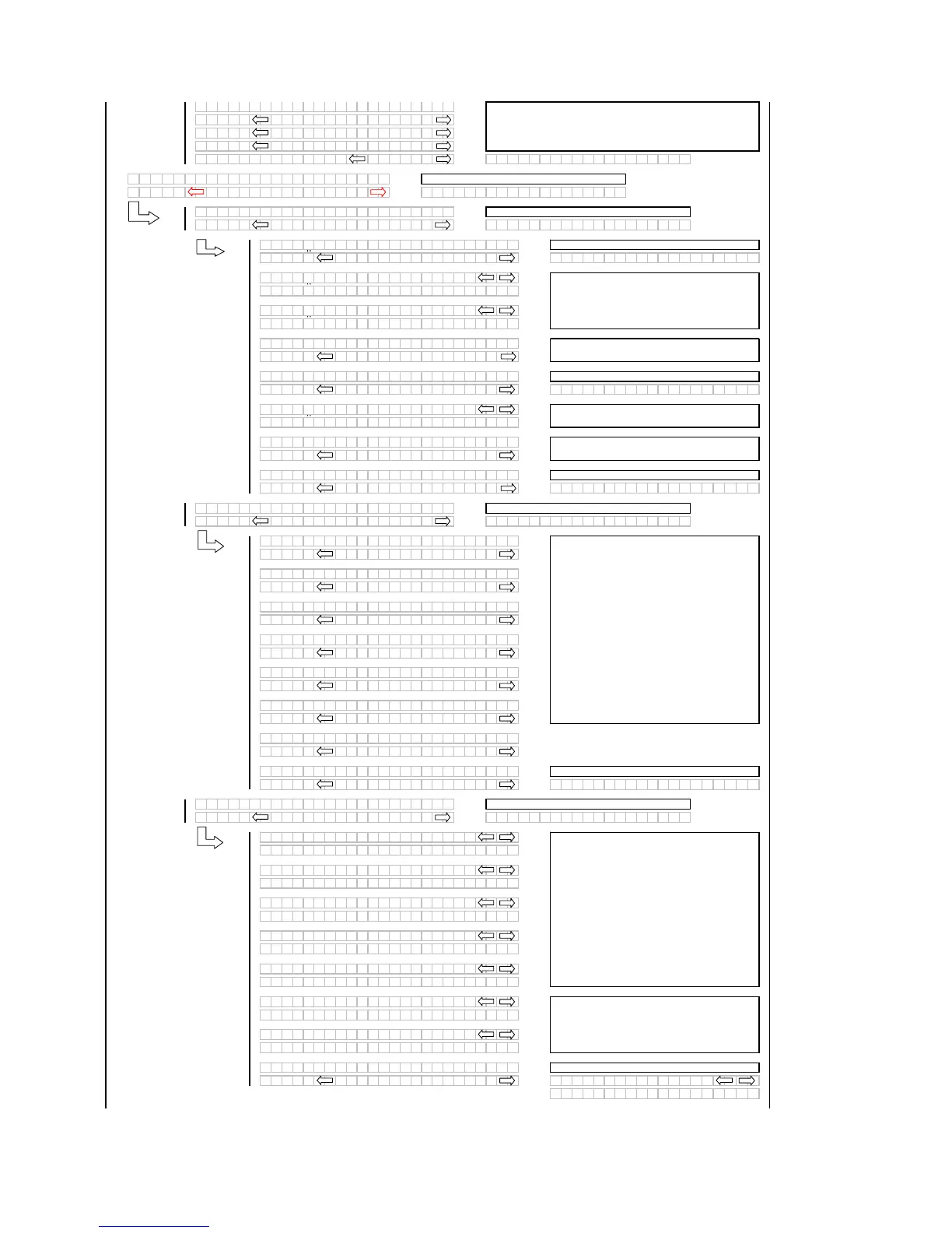
ES SENSOR I NPUT
HDR HE IGHT 3 . 5 9
For diagnostic purposes each sensors input
signal can be read. This helps in determining
how each sensor is operating and if the proper
output voltages are being received by the control
system.
If "NO" then jump to:
If "NO" then jump to:
The last 10 distinct error codes are stored along
with the code #, Exxx, engine hours and number
of occurrences. The "arrow" keys are used to
cycle between codes.
If "NO" then jump to the first error code logged.
If "NO" then jump to the first engine error code
logged.
Select any of the sensors by using the turn signal switches to
cycle through the choices. Pressing SELECT will take the
operator to the calibration menu for that particular sensor. NO is
the default for EXIT CAL?. If "NO" then jump to:
If "NO" then jump to:
If "NO" then
ump to:
If "NO" then jump to:
If "NO" then jump to:
The operator can select each sensor and
selectively enable or disable the sensor. This can
be used to disable a failed sensor to eliminate
false or erratic display readings.
When "SELECT" is pressed the program goes to
the EXIT SENSOR SETUP? menu selection.
If "NO" then jump to:
When "SELECT" is pressed the program goes to the
EXIT READ SENSORS? menu selection.
If "NO" then
ump to:
If "NO" then jump to:
The last 10 distinct error codes are stored.