4. Specifications
4.1. Interface specifications
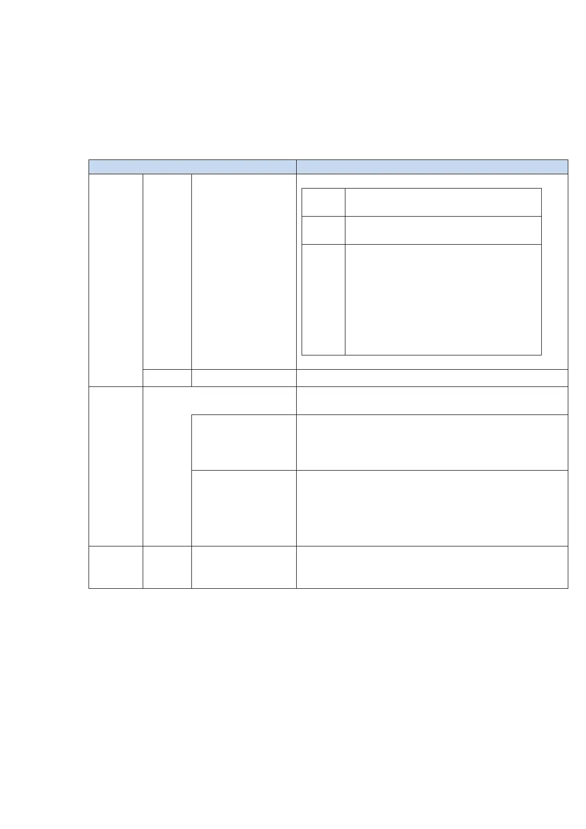
Setting switch×2 pcs. (Hexadecimal output 8bit)
「Setting mode」
IP address will be fixed to 192.168.100.1
「IP address setting for measurement」
Set lower 1byte of IP address with switches.
Example:
Set the upper 3bytes of the IP address with
Windows application to 192.168.0.__., then turn
the IP address setting switches to “A” for
192.168.0.”10.”
Refer to 4.2 LED indicator
RJ-45×2(100BASE-TX)
Shielded cable.
EtherNet/IP
communication
・Transmits the count value, error status, and calculation result
obtained from the measuring unit.
・Receives commands from the host device.
・The communication standard is the EtherNet/IP specification.
・When switches are set to “0x00”, MG80-EI enters “Setting mode”
with IP address fixed to 192.168.100.1. for TCP/IP communication.
This allows IP address and parameters to be changed, using
application for Windows PC.
All modules and measuring units connected to MG80-EI are supplied
from this power supply terminal.