2. Basic informaion
EtherNet/IP uses the terms “scanner” and “adapter” in place of “master” and “slave”,
respectively. MG80-EI is the adapter.
This section shows the adapter (MG80-EI) side components and its configuration,
which names and terms also appear in other sections of this manual.
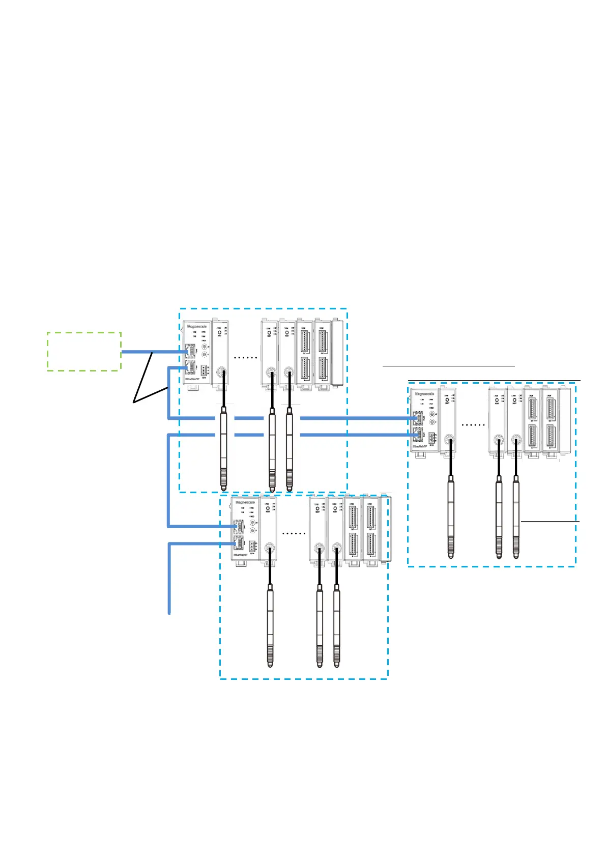
2.1. System configuration
The following diagram shows the example of maximum configuration using MG80
series lineup. A counter module MG80-CM is necessary for a connecting a measuring
unit, and I/O module LZ80-K1/K2 which enables control of the units with external
signal, are available for configuration with MG80-EI.
EtherNet/IP or
Ethernet cable
(MG80-EI side
RJ-45 connector)
Maximum configuration(1unit)※:
MG80-EI×1, MG80-CM×16, LZ80-K1/K2×2
※Up to 255 units(4080axis) can be connected
Measuring unit No. 1・・・・・・・・・・・15 16
・Up to 16 counter module MG80-CM can be connected to one MG80-EI.
・Connect the measuring unit DK series to MG80-CM.
・Measuring unit numbers are automatically assigned in order from 1 closest to MG80-EI.
・For EtherNet/IP or Ethernet connection, prepare a shielded cable with RJ-45(8P8C) connector.
(Both straight and cross cables can be used.)
・The number of connectable unit depend on the available lower 1byte of the IP address.
If the available IP address is 1 (0x01) to 255(0xFF), maximum of 255units of MG80-EI
(4,080 axes of measuring units) can be connected.