3
57-640 Eclipse
®
SIL Functional Safety Manual
1.0 Introduction
1.1 Product Description
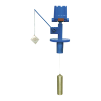
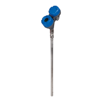
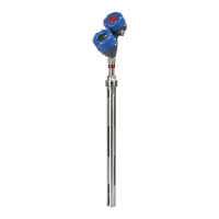
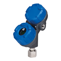
The Eclipse
®
Enhanced Model 705 Guided Wave Radar
Level Transmitter is a loop-powered, 24 VDC level trans-
mitter, based on Guided Wave Radar (GWR) technology.
For Safety Instrumented Systems usage it is assumed that
the 4–20 mA output is used as the primary safety variable.
The analog output meets NAMUR NE 43 (3.8 mA to
20.5 mA usable). The transmitter contains self-diagnostics
and is programmed to send its output to a user-selected
failure state, either low or high upon internal detection of a
failure. The device can be equipped with or without LCD
display. Table 1 lists the versions of the ECLIPSE Enhanced
Model 705 that have been considered for the hardware
assessment.
1.2 Theory of Operation
Guided Wave Radar is based upon the principle of TDR
(Time Domain Reflectometry). TDR utilizes pulses of elec-
tromagnetic energy transmitted down a probe. When a
pulse reaches a surface that has a higher dielectric than the
air/vapor in which it is traveling, the pulse is reflected. An
ultra high-speed timing circuit precisely measures the transit
time and provides an accurate level measurement.
The ECLIPSE Enhanced Model 705 is classified as a Type B
device according to IEC61508.
1.3 Determining Safety Integrity Level (SIL)
Tables 2 & 3 define the criteria for the achievable SIL
against the target mode of operation in Demand Mode
Operation.
Table 1 shows the relationship between the Safety Integrity
Level (SIL) and the Probability of Failure on Demand
Average (PFDavg).
Table 2 can be used to determine the achievable SIL as a
function of the Hardware Fault Tolerance (HFT) and the
Safe Failure Fraction (SFF) for the complete safety system
(type B – complex components as per IEC 61508 Part 2) of
which the level transmitter is one component.
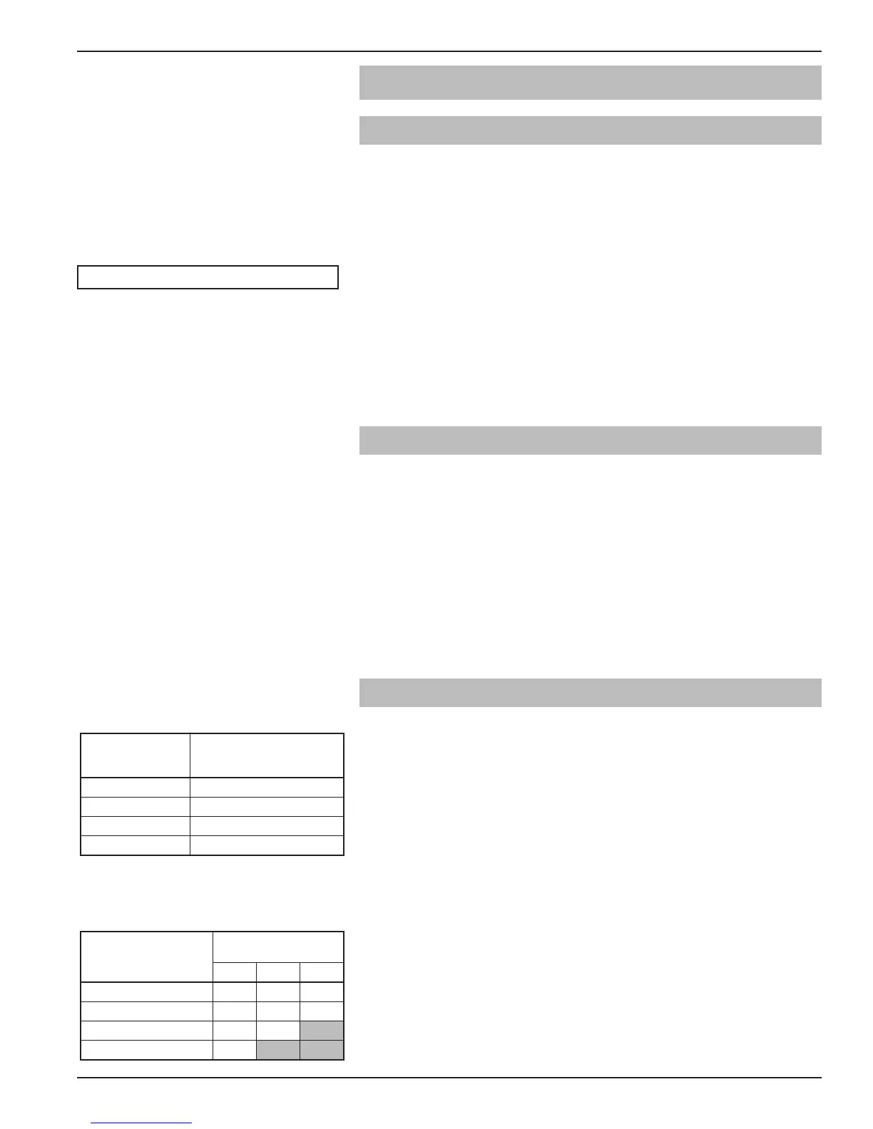
Model 705, 705-510*-*** (HART)
Table 3
Minimum hardware fault tolerance
Type B sensors, final elements and non-PE logic solvers
SFF
Hardware Fault
Tolerance (HFT)
0 1 2
None: <60%
Not
Allowed
SIL 1 SIL 2
Low: 60% to <90% SIL 1 SIL 2 SIL 3
Medium: 90% to <99% SIL 2 SIL 3
High: ≥99% SIL 3
Table 2
SIL vs. PFDavg
Table 1
Enhanced Eclipse
®
Model Numbers
Safety
Integrity Level
(SIL)
Target Average
probability of failure
on demand (PFDavg)
4 ≥10
-5
to <10
-4
3 ≥10
-4
to <10
-3
2 ≥10
-3
to <10
-2
1 ≥10
-2
to <10
-1
 Loading...