4
57-650 Eclipse
®
SIL Functional Safety Manual
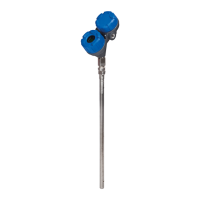
2.0 Level Measuring System
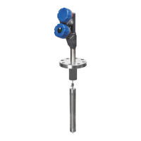
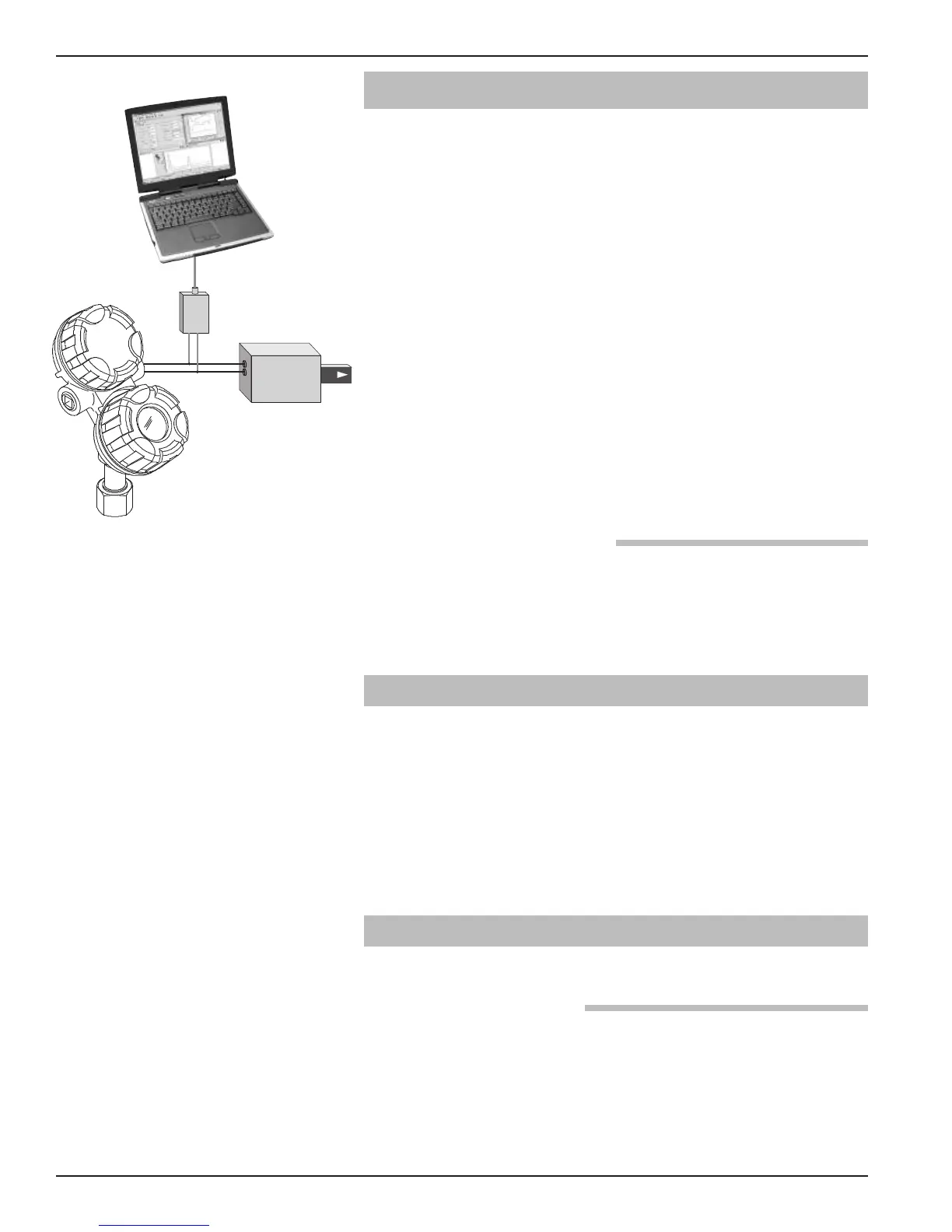
The diagram shows the structure of a typical measuring
system incorporating the Enhanced MAGNETROL
Model 705 guided wave radar transmitter.
This SIL rated device is only available with an analog signal
(4–20 mA) with HART communications. The measure-
ment signal used by the logic solver must be the analog
4–20 mA signal proportional to the level generated.
For fault monitoring, the logic unit must recognize both
high alarms (≥ 21.5 mA) and low alarms (≤ 3.6 mA). If the
logic solver loop uses intrinsic safety barriers caution must
be taken to insure the loop continues to operate properly
under the low alarm condition.
The only unsafe mode is when the unit is reading an incor-
rect level within the 4-20mA range (> ±2% deviation).
MAGNETROL defines a safe failure as one in which the
4-20 mA current is driven out of range (i.e., less than 3.8
mA or greater than 20.5 mA).
2.0.1 FOUNDATION fieldbus
™
Although the Enhanced Model 705 is available with
F
OUNDATION fieldbus
™
output, the FOUNDATION fieldbus
™
protocol has not been added to the IEC 61508/61511
standard.
2.1 Applicable Models
This manual is only applicable to the following model
numbers of Guided Wave Transmitter:
705-51Ax-xxx (SIL 2, HFT 0) and 705-510x-xxx (SIL 1,
HFT 0)
The primary difference between the two transmitter models
is the additional firmware diagnostics necessary to achieve
the safety levels required for SIL 2.
2.2 Miscellaneous Electrical Considerations
Following are miscellaneous electrical issues to be considered.
2.2.1 Pollution Degree 2
The ECLIPSE system is designed for use in Category II,
Pollution Degree 2 installations.
A nonconductive pollution of the sort where occasionally a
temporary conductivity caused by condensation must be
expected. This is the usual pollution degree used for equip-
ment being evaluated to IEC/EN 61010.
Actuator
PACTware
™
HART Modem
Eclipse
®
Model 705
Logic
Unit
Figure 1
Typical System
 Loading...