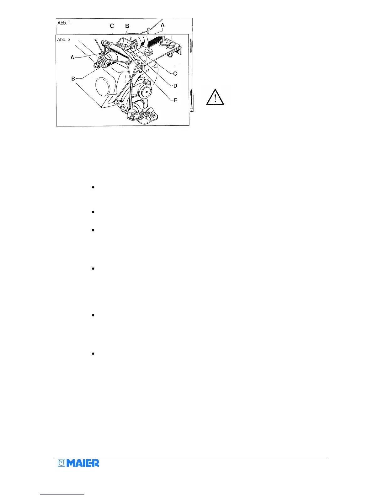
Machine without thread cutter (Fig. 1)
The thread is run over the thread stand through the thread guide A, the rear thread
eyelet, between the thread tensioning discs C (not round the pin), through the front
thread eyelets D (right-hand hole) and through the hole on the needle claw E.
The needle is threaded upwards from below. Move the needle lever to the extreme
left position for threading.
The thread eyelet D offers three possibilities for threading. In conjunction with the
thread take-up cam, the tension of the sewn thread loop can be influenced in this
way. Normally the thread is run through the right-hand hole. However, running the
thread through the left-hand hole gives a slacker thread loop. The effect can be
increased further by turning the thread take-up cam (set collar).
Adjust the thread tension C as slack as possible. Excessive thread tension can cause
marks (thread pulls) on the outside of the material. Please use the correct thread
quality e.g. 120/single, 120/double, 200/double.
Machine with thread cutter (Fig. 2)
When using our thread cutter (Fig. 2), the machine is threaded in the same way as
shown in Fig. 1. In addition, however, the thread is also run through eyelet A and the
groove of the thread clamp B, through the hole in the base plate to the front thread
eyelet. Push back the flexible cap B to do this. As a result, the thread is clamped
during the cutting operation.
There must be approx. 0.2 mm play between the nuts and the angle flange, so that
the connection pin D together with the brake cap B can be turned or moved easily.
Also, connecting rod E must not bind.