Page 65Version 2023-06-15 Fire damper - FDMR
TPM 140/19
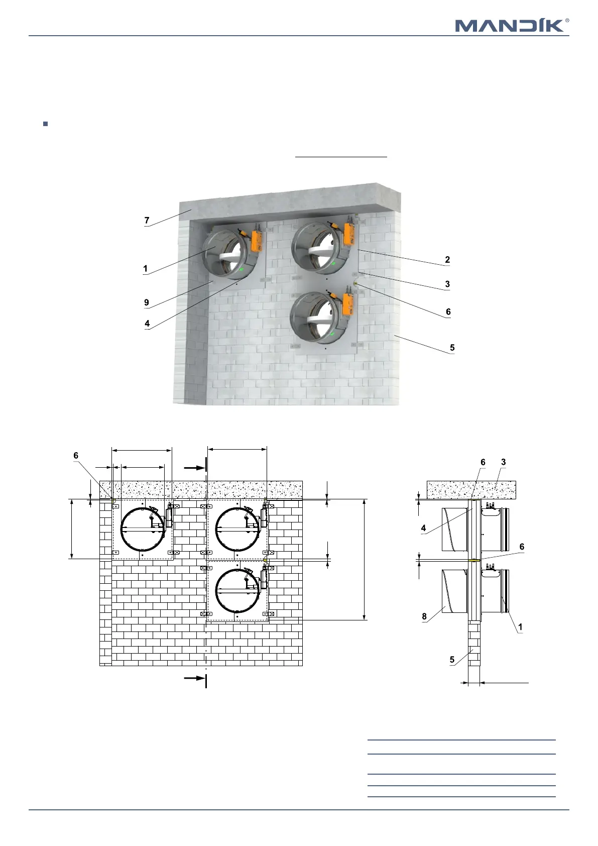
In solid wall construction - installation next to the wall/ceiling - installation frame R1, R2
■ For connection of following duct → see page 90
■ Installation frame can be installed on the damper or delivered separately
■ Installation procedure of the installation frame for FDMR → see manual
Installation frame R1 - solid wall th. 100 mm or solid ceiling th. 110 mm
■ Installation frame R2 - solid wall th. 150 mm or solid ceiling th. 150 mm
■ Conditions of this installation are also valid for the installation in Solid ceiling construction
■ Mineral wool is fixed to the wall construction and to the installation frame with fire-protective mastic
EIS 90
A
A
ØD
Ø
D+155
+3
(installation open-
ing)
2xØD+315
+3
(installation opening)
≥ 100 (R1)
≥ 150 (R2)
20
10
20
A-A
10
10
Ø
D+145
+3
(installation open-
ing
)
Ø
D+155
+3
(installation open-
ing
)
10
1 FDMR
2 Installation frame
3 Bracket with fasteners (delivered with frame)*
4 Fill the gaps with glue PROMAT K84
5 Solid wall construction
6 Mineral wool board - min. density 140 kg/m³ (e.g. PROMAPYR-T150)
7 Solid ceiling construction
8 Duct
9 Bracket L with fasteners (if required - must be specified in the order)
* Bracket with fasteners for 1 damper
FDMR diameter
Number of
brackets
Number of
screws
D ≤ 400 4 8
400 < D ≤ 800 8 16