Page 87Version 2023-06-15 Fire damper - FDMR
TPM 140/19
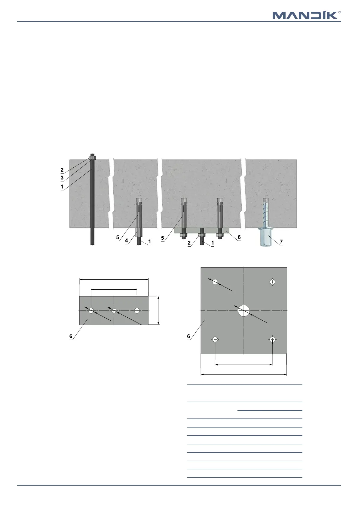
Hinge plates
2xØ9
M8 to M16
120
80
50
4x
Ø
9
M20
100
150
■ If in doubt, always consult an anchor specialist
engineer such as Halfen or Hilti.
1 Threaded rod M8 - M20
2 Nut M8 - M20
3 Washer for M8 - M20
4 Coupling Nut M8 - M20
5 Anchor
6 Hinge plate - min. thickness 10 mm
7 Concrete screw tested for fire resistance R30-R90,
max. Tension up to 0.75 KN (length 35 mm)
Load capacities of threaded rods F [N] at the
required fire resistance 90 minutes
Size As [mm²]
Weight G [kg]
for 1 piece for 1 pair
M8 366 22 44
M10 58 35 70
M12 843 52 104
M14 115 70 140
M16 157 96 192
M18 192 117 234
M20 245 150 300
Without anchor With anchor
Examples of anchoring to the ceiling construction
Follow the instructions of fixing specialist or installation company
With hinge plate and anchors
Screw with internal
thread and hexagon drive
■ The dampers must be suspended using threaded rods and
mounting profiles. Their dimensioning depend on the
weight of the damper.
■ The dampers and the duct must be suspended separately.
■ Following air-conditioning duct must be suspended or
supported so that all load transfer from the following duct
to the damper flanges is absolutely excluded. Adjacent
duct must be suspended or supported, as required by the
duct suppliers.
■ Threaded rods longer than 1,5 m must be protected by
fire insulation.
Mounting to the ceiling wall
V. SUSPENSION SYSTEMS