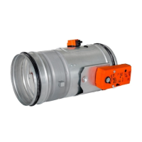
Fire damper - FDMRPage 86 Version 2023-06-15
TPM 140/19
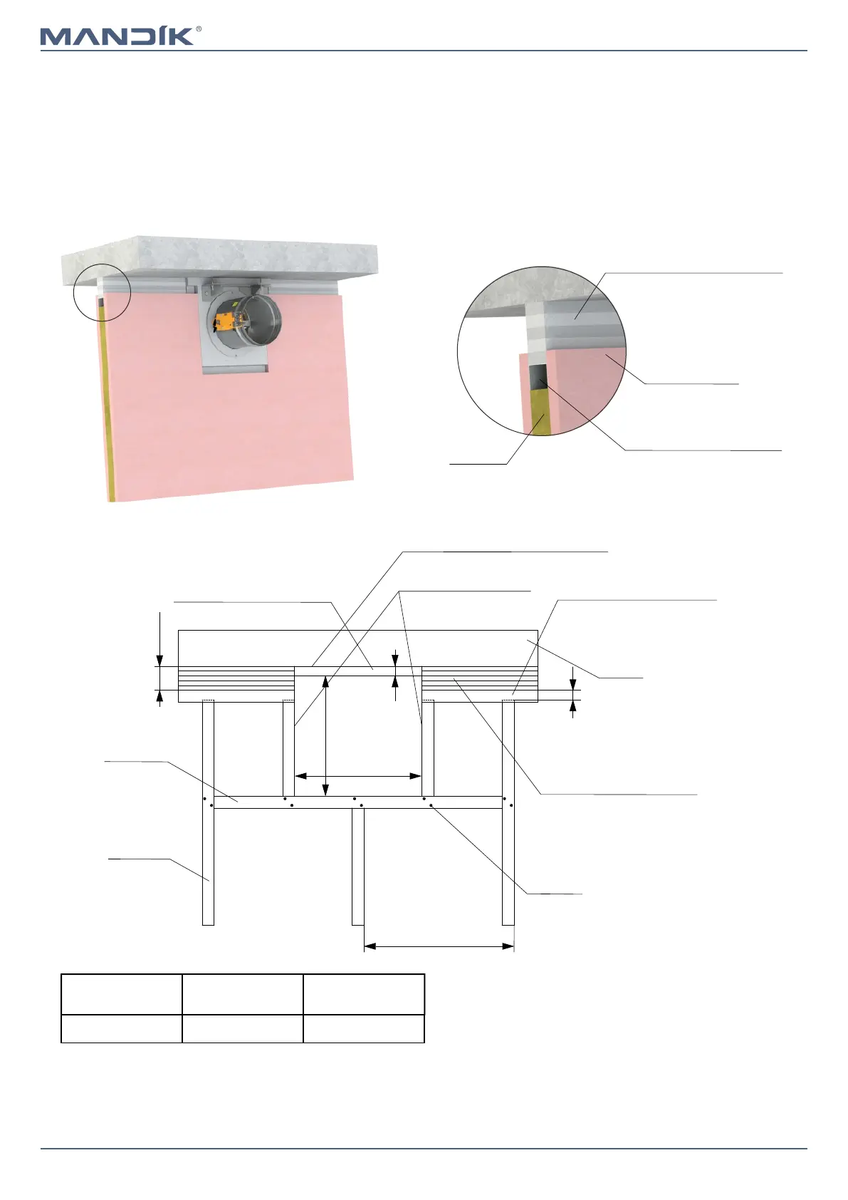
Installation at a maximum distance of 80 mm from the ceiling
EIS 90
* Width of the boards for frame R7 = 100 mm
≤ 625
2x screw
CW-Profile
UW-Profile
Connection of the flexible
ceiling according to wall
specifications
Ceiling
Z
W
X+Y+20
Y
X
UW-profile (screwed to the con-
nection of the flexible ceiling)
* Cement-lime boards filling -
min. density 450 kg/m³
Closed sides of profile
Apply intumescent sealant between
the ceiling and boards
(e.g. Hilti CP611A, Promaseal-AG)
■ Detailed instructions for installation R7 frame → see manual
■ For connection of following duct → see page 90
■ Installation frame can be installed on the damper or delivered separately
■ Installation procedure of the installation frame for FDMR → see manual
■ Gypsum construction must be made in accordance with the specifications of the wall system manufacturer
■ X = ceiling movement = 10 to 40 mm
■ F = gap between frame (promaseal) and profile = 2 to 5 mm
■ Y = distance of frame from ceiling max. 80 mm
Installation frame
W
[mm]
Z
[mm]
R7
ØD + 208 + X + Y + F ØD + 276 + (2 x F)
Connection of the flexible ceiling
according to wall specifications
UW-profile (screwed to the
connection of the flexible
ceiling)
Gypsum boards
Insulation