Page 73Version 2023-06-15 Fire damper - FDMR
TPM 140/19
EIS 90
≥ 110 (R3)**
≥ 150 (R4)**
Ø
D
ØD+130
Ø
D+115
+3
(installation opening
)
Ø
D+115
+3
(installation opening)
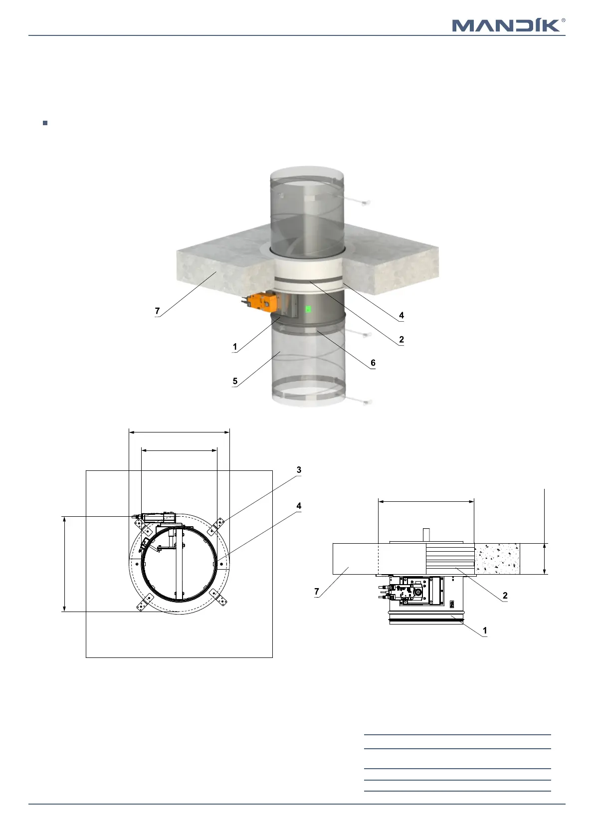
■ For connection of following duct → see page 90
■ Installation frame can be installed on the damper or delivered separately
■ Installation procedure of the installation frame for FDMR → see manual
Installation frame R3 - ceiling th. 110 mm**
■ Installation frame R4 - ceiling th. 150 mm**
In solid ceiling construction - installation frame R3, R4
* Bracket with fasteners for 1 damper
FDMR diameter
Number of
brackets
Number of
screws
D ≤ 400 4 8
400 < D ≤ 800 8 16
** min. 110 mm - Concrete - for EIS 90 - Installation frame R3
min. 125 mm - Aerated concrete - for EIS 90 and EIS 120 - Installation frame R3
min. 150 mm - Concrete - for EIS 120 - Installation frame R4
1 FDMR
2 Installation frame
3 Bracket with fasteners (delivered with frame)*
4 Fill the gaps with glue PROMAT K84
5 Duct
6 Clamp with threaded rod → see pages 87 to 89
7 Solid ceiling construction