Fire damper - FDMRPage 80 Version 2023-06-15
TPM 140/19
■ For connection of following duct → see page 90
■ The duct must be suspended or supported on both sides of the damper acc. to national rules
■ Load of the suspension system depends on weight of the fire damper and duct system → see page 87
■ Max. distance between two suspension systems is 1500 mm
■ Following air-conditioning duct must be suspended or supported so that all load transfer from the following duct to the fire damper is
absolutely excluded. Adjacent duct must be suspended or supported, as required by the duct suppliers
■ Installation frame can be installed on the damper or delivered separately
■ Installation procedure of the installation frame for FDMR → see manual
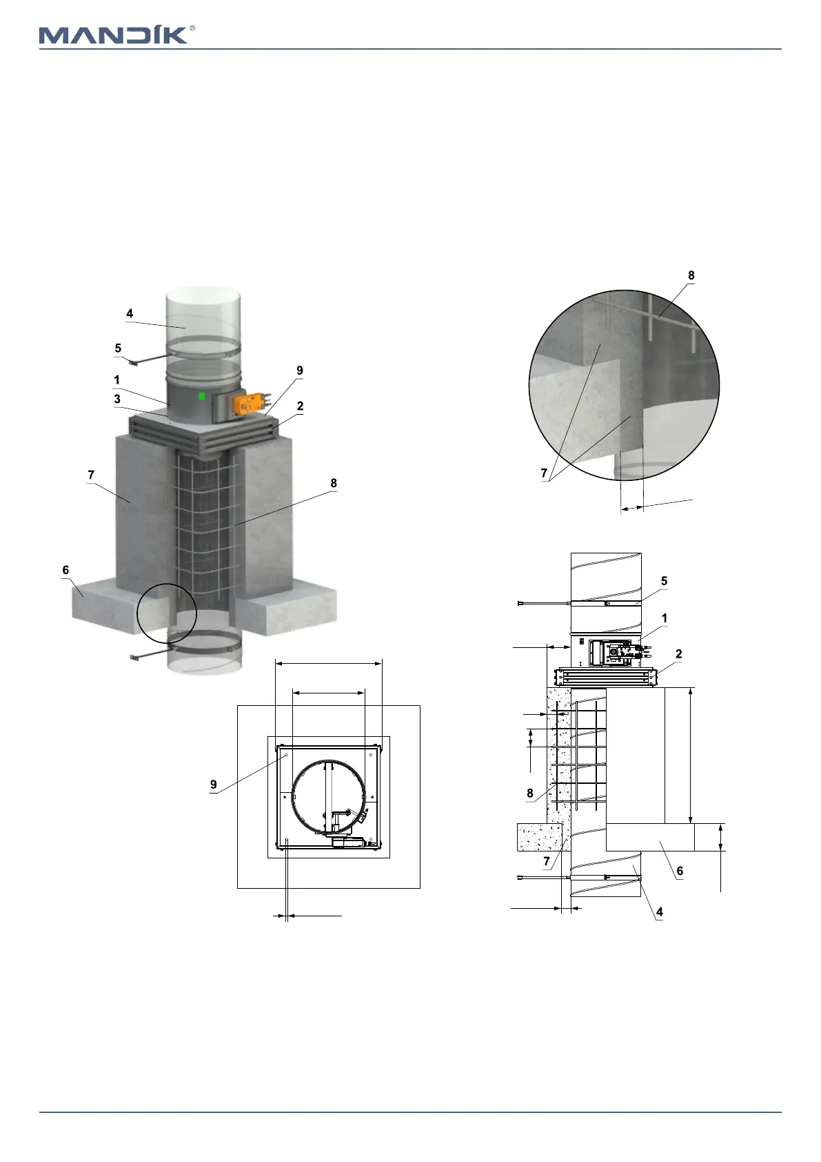
Outside solid ceiling construction - concreting - installation frame R5
1 FDMR
2 Installation frame - apply HILTI CFS-S ACR mastic at the entire area and
glue it to the fire separating construction
3 Fill the gaps with glue PROMAT K84
4 Standard air duct, made of galvanized sheet metal min. thickness 0,8 mm
5 Clamp with threaded rod → see pages 87 to 89
6 Solid ceiling construction
7 Concrete B20
8 Rebar - steel rod Ø 6 mm, mesh hole 100 mm
9 Holes for fixing the frame with threaded rods or steel anchors (frame
fixing material not included)
50...150
EIS 90
≥ 110*
≤ 750
50...150
100
≥
100
30
A
4 x
Ø
12
ØD
X
A
* min. 110 mm - Concrete
min. 125 mm - Aerated concrete
X = ØD+120 for dampers ØD 100-200 mm
X = ØD+167 for dampers ØD 225-800 mm