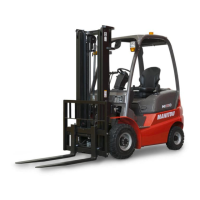
16 - SINGLE OR DUAL EFFECT REAR HYDRAULIC CONTROL PREDISPOSITION
16 - SINGLE OR DUAL EFFECT REAR HYDRAULIC CONTROL PREDISPOSITION
Enables the use of a hydraulic rear hook or of a trailer with hydraulic tipping.Enables the use of a hydraulic rear hook or of a trailer with hydraulic tipping.
-- Single or double effect rear hydraulic control functions Single or double effect rear hydraulic control functions with hydraulic control of thewith hydraulic control of the
additional attachment (see chapter: 2 - DESCRIPTION: 20 - HYDRAULIC CONTROLS)additional attachment (see chapter: 2 - DESCRIPTION: 20 - HYDRAULIC CONTROLS)
according to the position of tap 1.according to the position of tap 1.
- Position A: Hydraulic control of the additional attachment at the front of the lift- Position A: Hydraulic control of the additional attachment at the front of the lift
truck.truck.
- Position B: Hydraulic control of the additional attachment at the rear of the lift- Position B: Hydraulic control of the additional attachment at the rear of the lift
truck.truck.
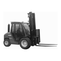
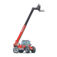
17 - ATTACHMENT HYDRAULIC CONTROL FORCED OPERATION17 - ATTACHMENT HYDRAULIC CONTROL FORCED OPERATION
This OPTION must only be used with an attachment requiring continuous hydraulic movement of type:This OPTION must only be used with an attachment requiring continuous hydraulic movement of type:
brush, supply bucket, mixer, spray… It is strictly forbidden in brush, supply bucket, mixer, spray… It is strictly forbidden in handling operations and at all handling operations and at all other eventsother events
(winch, crane jib, crane jib with winch, hook, etc.).(winch, crane jib, crane jib with winch, hook, etc.).
COCONTINTINUNUOUOUSS HYDHYDRARAULIULICC MOMOVEMVEMENTENT OFOF THETHE AATTTTACACHMHMENTENT
- Make sure th- Make sure the potentiometer C e potentiometer C is set to is set to 00 %.%.
-- Switch button A to the front or the back (Switch button A to the front or the back (depending on the type of attachment)depending on the type of attachment), press button, press button
B and release button A. The red indicator 1, flashes to indicate that it is in operation.B and release button A. The red indicator 1, flashes to indicate that it is in operation.
- Set the required flowrate - Set the required flowrate using potentiometer C.using potentiometer C.
-- To sTo stop continuous hydraulic movement of top continuous hydraulic movement of the attachment, move switch A forwards orthe attachment, move switch A forwards or
backwards or press button B. Indicator 1 backwards or press button B. Indicator 1 goes out.goes out.
- Set pot- Set potentiomentiometer C to 0eter C to 0 %.%.
Never leave the driver’s cab without resetting the potentiometer C to 0 %. Before starNever leave the driver’s cab without resetting the potentiometer C to 0 %. Before starting the lift truck,ting the lift truck,
make sure the potentiometer is set to 0 make sure the potentiometer is set to 0 %.%.
NOTE:NOTE: If the operator leaves the driver’s If the operator leaves the driver’s cab, the continuous hydraulic movement willcab, the continuous hydraulic movement will
automatically stop and must be restarted.automatically stop and must be restarted.
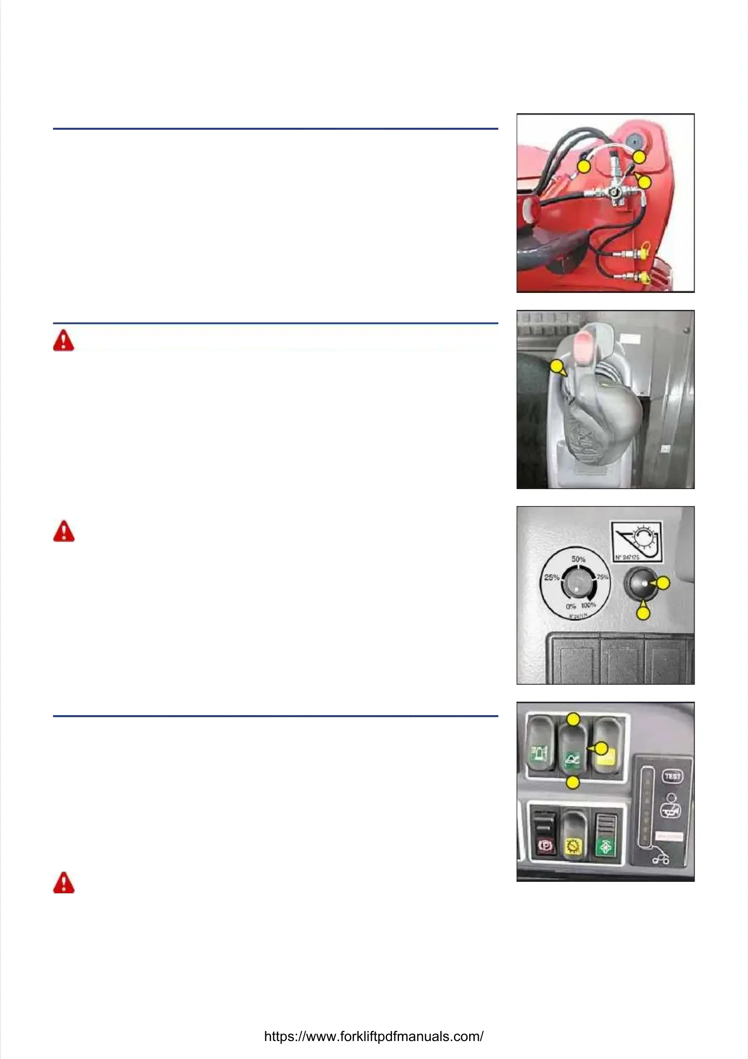
18 - JIB SUSPENSION18 - JIB SUSPENSION
The jib is suspended to reduce shaking of the lift truck on rough ground (e.g. moving strawThe jib is suspended to reduce shaking of the lift truck on rough ground (e.g. moving straw
in a field).in a field).
OPERATIONOPERATION
-- Set the forks or attaSet the forks or attachment on the ground and relieve the front wheels chment on the ground and relieve the front wheels a few centimetresa few centimetres
only.only.
-- Press switch 1 set to position A, the visual indicator comPress switch 1 set to position A, the visual indicator comes on indicating that jib suspensiones on indicating that jib suspension
is activated.is activated.
-- Press switch 1 set to position B, thPress switch 1 set to position B, the visual indicator goes out indicating that jib suspense visual indicator goes out indicating that jib suspensionion
is deactivated.is deactivated.
Jib suspension is active to a lifting height of 3m00 from the axis of articulation of the carriage withJib suspension is active to a lifting height of 3m00 from the axis of articulation of the carriage with
respect to the ground with the jib retracted. When you move beyond this height or make anotherrespect to the ground with the jib retracted. When you move beyond this height or make another
hydraulic movement (tilting, telescoping, attachment), jib suspension is momentarily deactivated andhydraulic movement (tilting, telescoping, attachment), jib suspension is momentarily deactivated and
the visual indicator of switch 1 goes out.the visual indicator of switch 1 goes out.
- When the I.C. engine is off, jib suspension is automatically deactivated.- When the I.C. engine is off, jib suspension is automatically deactivated.
11
BB
AA
11
AA
BB
AA
BB
11
 Loading...