Manitowoc Published 07-23-15, Control # 078-03 6-5
31000 LUFFING JIB OPERATOR MANUAL MAINTENANCE
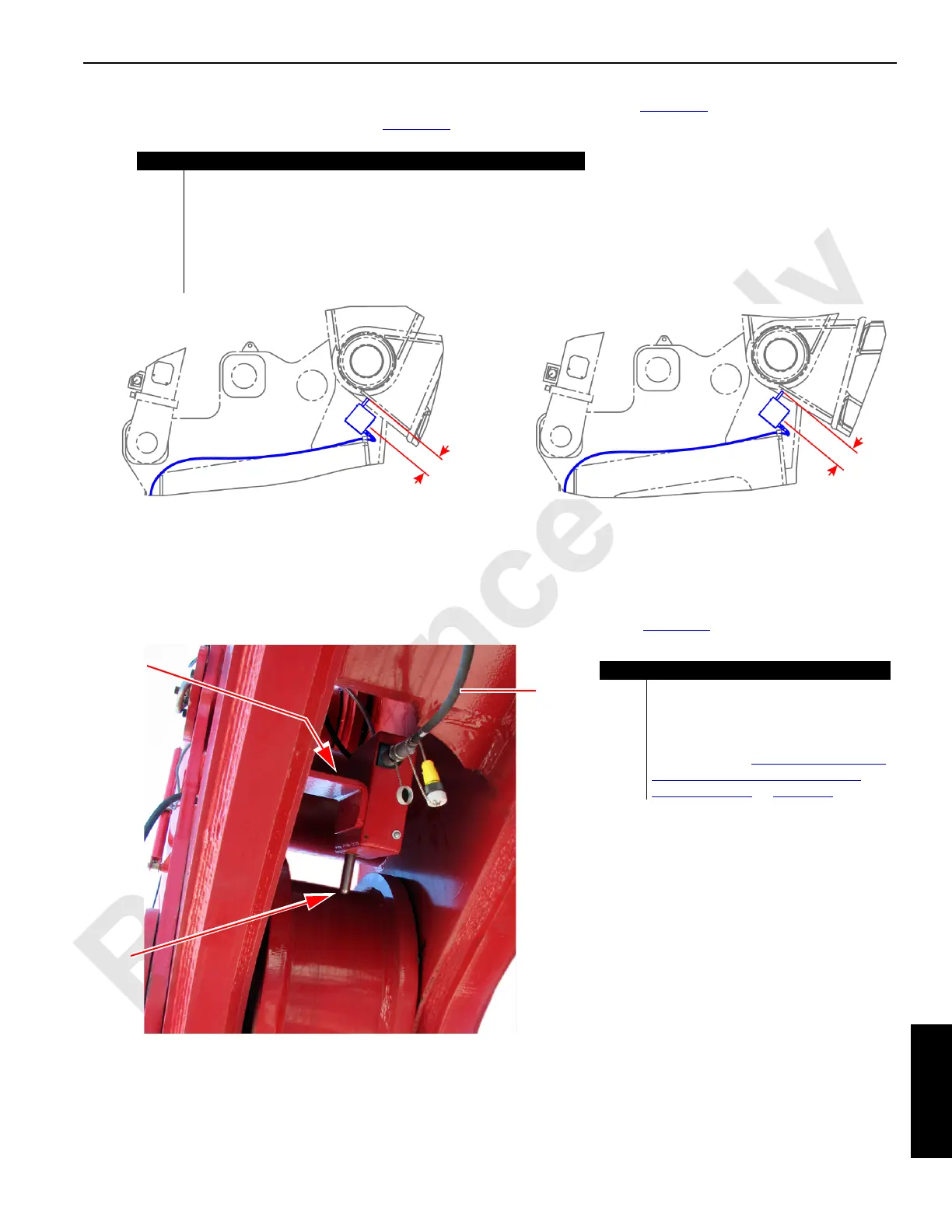
1. The luffing jib-to-boom minimum angle switch (A) should be mounted as shown in Figure 6-2. Activated and non-activated
positions of the actuator rod are shown in Figure 6-3
:
2. To determine the position of the actuator rod on the luffing jib-to-boom minimum angle switch (A), measure the distance
between the angle switch mount back (B) and the actuator rod tip (C) as shown in Figure 6-4
:
FIGURE 6-3
Item Description
A Luffing jib-to-boom minimum angle switch.
B #91 luffing jib butt.
C #90 boom top.
D 174.2mm = actuated position of actuator rod.
E 180.0mm = non-actuated position of actuator rod.
F W203 cable (see Remove the Luffing Jib Drum 5 Assembly and
Relocate the Wire Rope Guide on page 4-80).
A
A
B
B
C
C
D
E
F
F
Luffing jib-to-boom minimum angle switch
(actuated position)
Luffing jib-to-boom minimum angle switch
(non-actuated position)
FIGURE 6-4
Item Description
A Luffing jib-to-boom minimum angle
switch.
B Angle switch mount back.
C Actuator rod tip.
D W203 cable (see Remove the Luffing Jib
Drum 5 Assembly and Relocate the
Wire Rope Guide on page 4-80).
A
B
C
D

 Loading...


