SET-UP AND INSTALLATION 31000 LUFFING JIB OPERATOR MANUAL
4-74 Published 07-23-15, Control # 078-03
Upper Boom Point Installation — Method 2
Step Action
1
Information below from drawing A19443, Sheet 28:
Complete the hook block reeving (A):
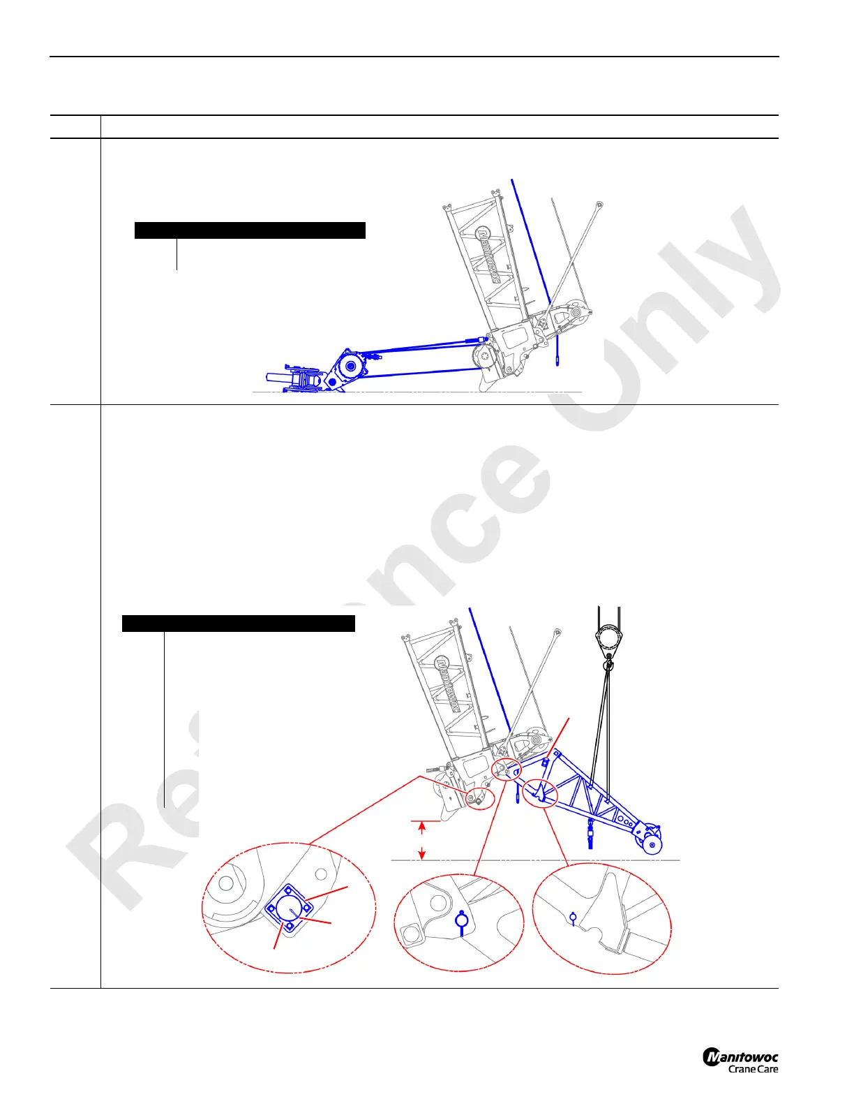
2
Information below from drawing A19443, Sheet 28:
• Boom up distance (A) to provide access to the upper boom point hinge pin (B) hole.
• Position the Drum 3 hoist rope (C) so that it does not interfere with the upper boom point installation (D).
• Use an assist crane (E) attached as shown below to secure the upper boom point (D) to the #91 luffing jib top (F)
with the upper boom point hinge pin (B).
• Remove locking pins (G) from the upper boom point (D). Keep these locking pins (G) as they will be needed to
lock the upper boom point (D) in place.
• Remove the load pins (H) and keeper plates (I) from the load pin storage location (J).
• Use the keeper plates (I) to secure the load pins (H) to the #91 luffing jib top (F). Note that the load pin arrow (K)
shall point towards the crane.
FIGURE 4-80
Item Description
A Hook block reeving.
B Drum 3 hoist line.
A
B
FIGURE 4-81
Item Description
A 203.2 cm (80 in).
B Upper boom point hinge pin.
C Drum 3 hoist rope.
D Upper boom point.
E Assist crane.
F #91 luffing jib top.
G Locking pin.
H Load pin.
I Keeper plates.
J Load pin storage location.
K Load pin arrow.
A
B
C
D
E
F
G
H
I
I
J
K