SET-UP AND INSTALLATION 31000 LUFFING JIB OPERATOR MANUAL
4-78 Published 07-23-15, Control # 078-03
Lower the Main Strut
15
Disconnect the jib straps from the link support set. Return the link support set to its shipping position (Figure 4-46).
Step Action
Step Action
16
Disconnect pendants, yoke, and snatch block from the main strut (Figure 4-45 and Figure 4-19).
17
Attach the yoke and pendants to an assist crane (Figure 4-39) Hoist up with the assist crane to take the slack out of
the pendants (10,000 to 15,000 pounds maximum).
18
Attach the Drum 6 winch wire rope to the main strut snatch block (Figure 4-19).
19
Hoist in the luffing jib until the load bearing areas of the connectors make contact (Figure 4-42). Use the Portable
Power Unit to retract the main strut connector pins (Figure 4-44
).
NOTE: There should be no slack in the Drum 6 winch wire rope (Figure 4-42
) in order to prevent the upper half of
the main strut from opening suddenly.
20
Slowly pay out the 34mm luffing hoist rope (Drum 5) while hoisting up the main strut top with an assist crane.
As the main strut sections open (Figure 4-41
), relieve tension on the 19mm Drum 6 winch wire rope and the 34mm
luffing hoist rope (Drum 5).
Disconnect the 19mm Drum 6 winch wire rope from the dead end on the wire rope guide (Figure 4-19
) and pay in
the 19mm wire rope to the Drum 6 winch (Figure 4-10
). Store the 19mm wire rope fittings in a storage box.
21
Continue to support the main strut top with an assist crane as the main strut folds down towards the jib strut.
Adjust the 34mm luffing hoist rope (Drum 5) as necessary during the lowering of the main strut to avoid tangling
wire rope in the strut inserts.
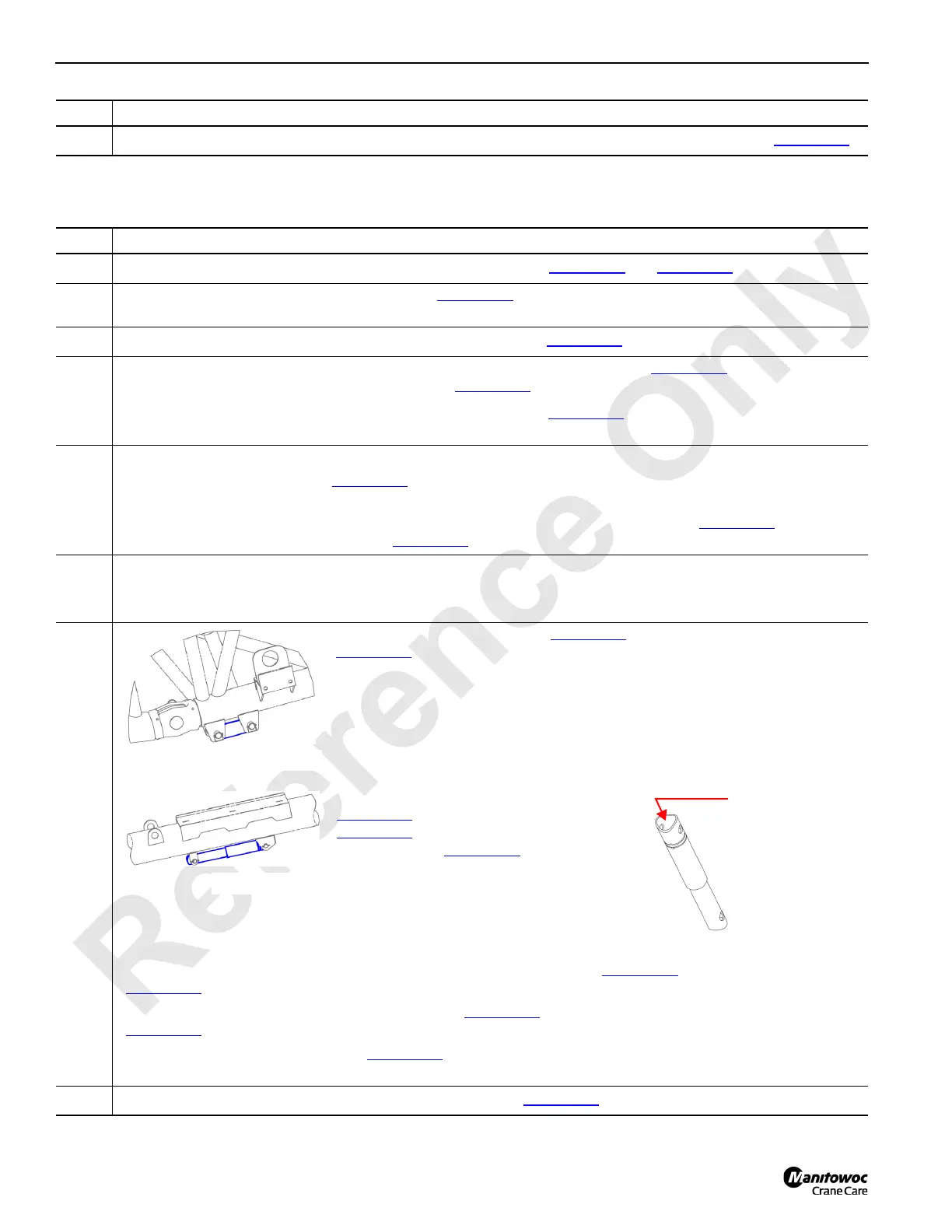
22
Pivot the main strut support strut (Figure 4-84) from its stowed position
(Figure 4-17
). Allow the support strut to hang vertically.
Pivot the main strut support stop strut
(Figure 4-85
) from its stowed position
(Figure 4-18
). Adjust this support strut to its
minimum length (Figure 4-86
). Failure to
adjust the main strut support stop strut to
its minimum length may cause structural
damage to the crane. Allow the support strut to
hang vertically.
Lower the main strut with the assist crane until the main strut support strut (Figure 4-84
) nests onto the jib strut butt
(Figure 4-17
).
Adjust the length of the main strut support stop strut (Figure 4-86
) until contact is made with the #90 boom top
(Figure 4-18
).
Pivot the long (or short) support strut (Figure 4-21
) from their stowed positions and attach to the main strut insert
below.
23
Disconnect the hydraulic lines from the jib backstay spreader (Figure 4-40) and rewind the lines on the reel.
FIGURE 4-85
M
a
i
n
s
t
r
u
t
s
u
p
p
o
r
t
s
t
o
p
FIGURE 4-86
Use the threaded
rod to adjust the
support strut length.

 Loading...


