SET-UP AND INSTALLATION 31000 LUFFING JIB OPERATOR MANUAL
4-4 Published 07-23-15, Control # 078-03
#91 LUFFING JIB INSTALLATION
In the following steps, except where noted, a 54 m (177.2 ft) #91 luffing jib will be attached to a 70 m (229.7 ft) #90 boom.
NOTE: For node and sensor wiring for the #91 luffing jib, see the Remove the Luffing Jib Drum 5 Assembly and Relocate the
Wire Rope Guide (page 4-80).
Set Up the Equalizer Insert
Step Action
1
Information below from drawing A19443, Sheet 8:
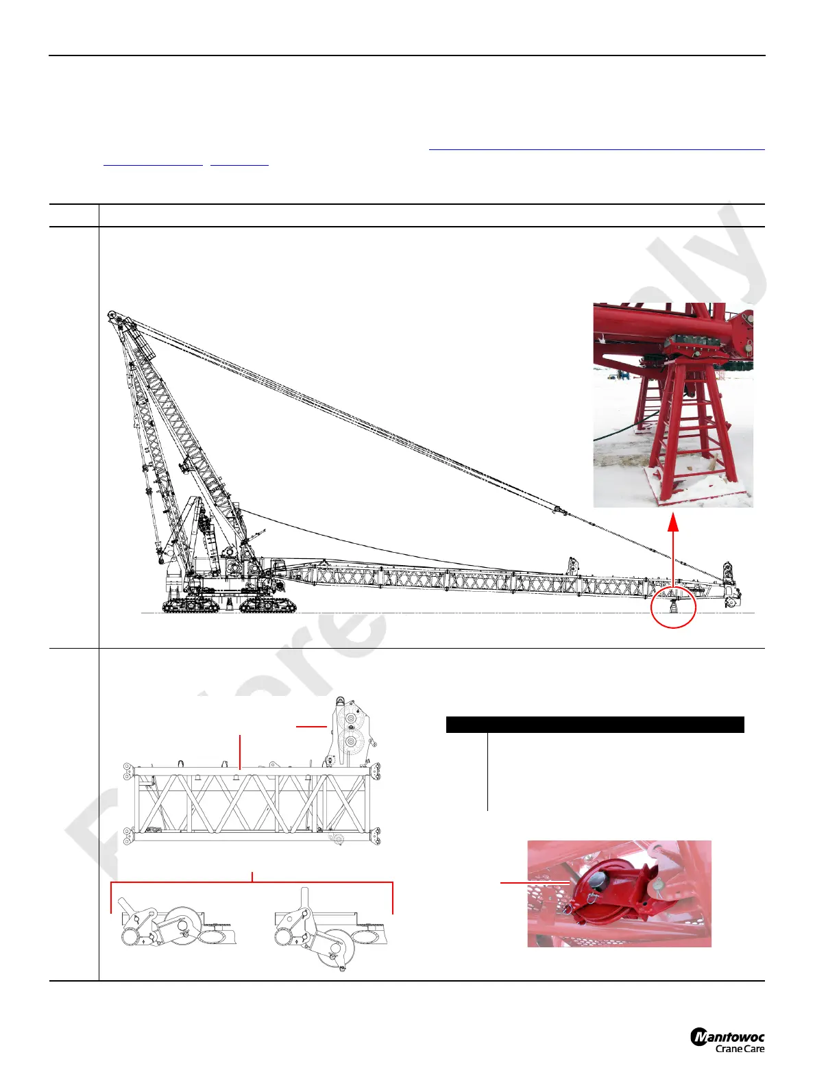
Assembly the #90 boom per luffing jib assembly drawings for the #91 luffing jib on #90 boom.
Then lower the boom on two boom stands that are placed under the end of the last insert before the boom top
insert:
2
Information below from drawing A19443, Sheet 8:
On the #90 boom 10 m (32.8 ft) equalizer insert, set the winch equalizer assembly to the working position:
A
B
C
D
C
Item Description
A #90 boom 10 m (32.8 ft) equalizer insert.
B Winch equalizer assembly.
C Winch equalizer assembly (stowed position).
D Winch equalizer assembly (working position).
E Wire rope guide.
E
FIGURE 4-3