Manitowoc Published 07-23-15, Control # 078-03 4-71
31000 LUFFING JIB OPERATOR MANUAL SET-UP AND INSTALLATION
Upper Boom Point Installation
• If reeving the lower boom point while the luffing jib is on a dolly OR if the boom-to-luffing jib included angle is 150°, then go
to Upper Boom Point Installation — Method 1
on page 4-71.
• If reeving the lower boom point while the luffing jib is on the ground or on blocking OR if the boom-to-luffing jib included
angle is either 70° or 90°, then go to Upper Boom Point Installation — Method 2
on page 4-74.
Upper Boom Point Installation — Method 1
Step Action
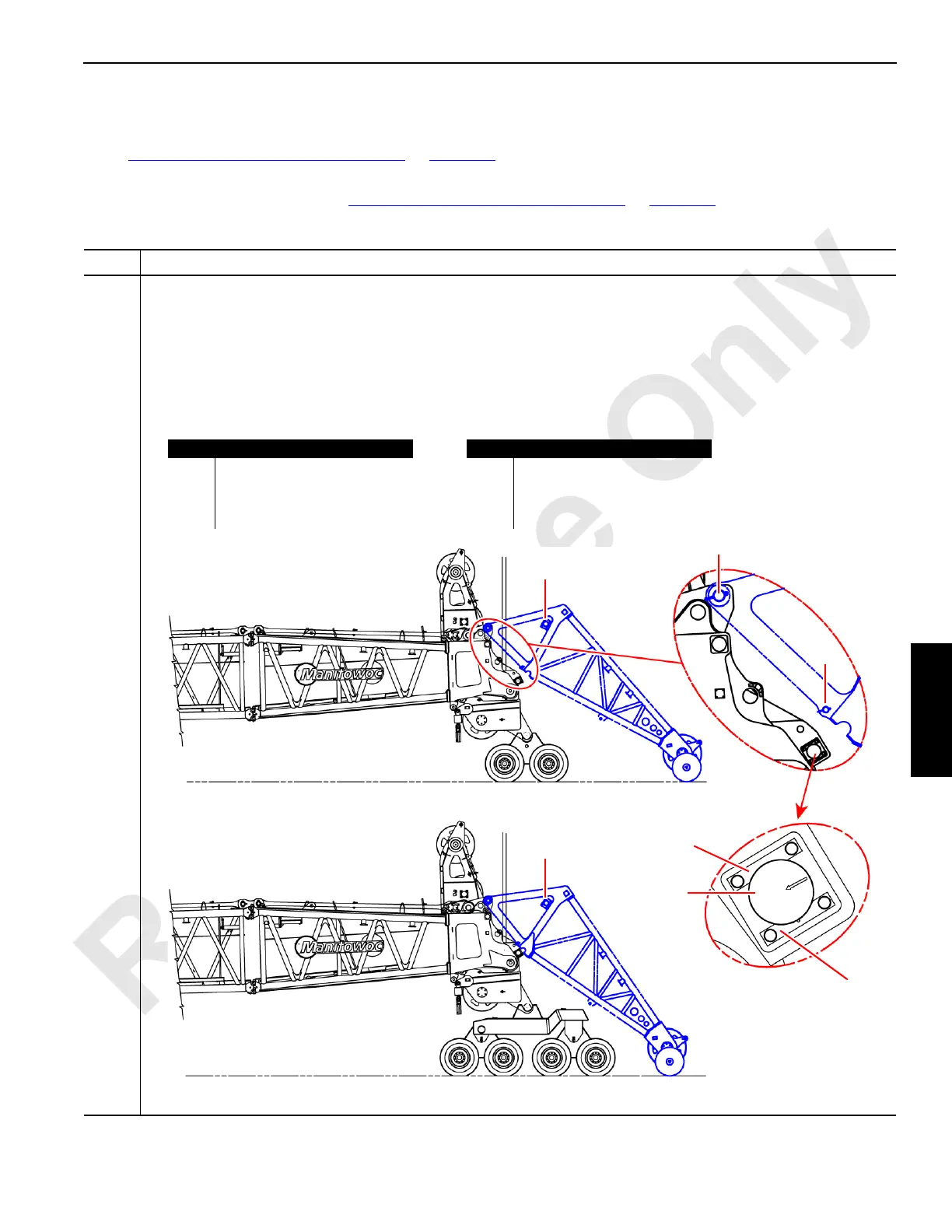
1
Information below from drawing A19443, Sheet 28:
• Secure the upper boom point (A) to the #91 luffing jib top (B) at the upper hinge pin (C).
• Remove the retaining pin (F) from the #91 luffing jib top (B).
• Remove the load pin (E) from the load pin storage (D) on the upper boom point (A). Also remove the fastener
hardware from the #91 luffing jib top (B).
• Attach the load pin (E) using keeper plates (G). The load pin (E) shall be positioned so that the arrow inscribed
on the pin (H) points toward the lower point sheave bank as shown.
FIGURE 4-77
Item Description
A Upper boom point.
B #91 luffing jib top.
C Upper hinge pin.
D Load pin storage.
A
B
E
A
B
D
D
F
G
G
H
C
Item Description
E Load pin.
F Retaining pin.
G Keeper plate.
H Load pin arrow.
Configuration for #91 Luffing Jib Lengths less than 72 m (236.2 ft)
Configuration for #91 Luffing Jib Lengths equal to greater than 72m (236.2 ft)