MAINTENANCE 31000 LUFFING JIB OPERATOR MANUAL
6-8 Published 07-23-15, Control # 078-03
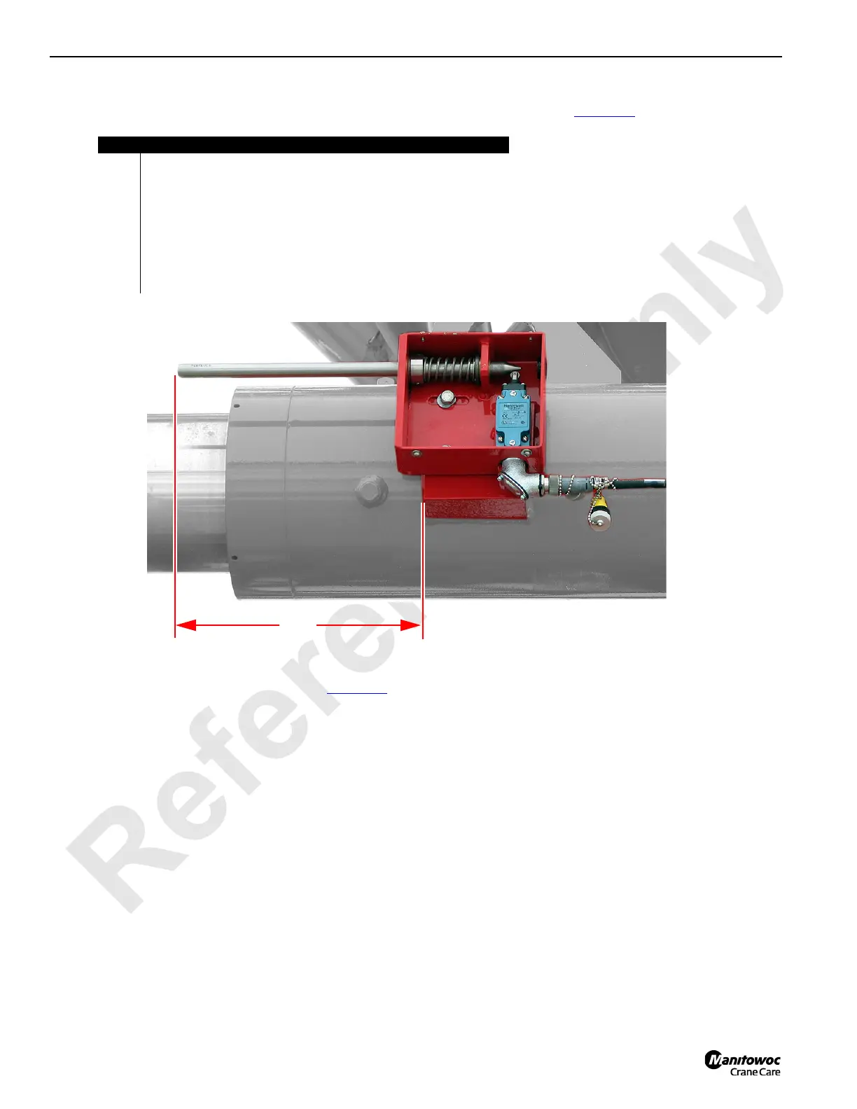
2. To determine the position of the actuator rod on the luffing jib-to-boom maximum angle switch (A), measure the distance
between the angle switch mounting block (B) and the actuator rod tip (C) as shown in Figure 6-7
:
3. To adjust the actuator rod position (D), see Figure 6-5
.
FIGURE 6-7
Item Description
A Luffing jib-to-boom maximum angle switch.
B Mounting block.
C Actuator rod.
D Actuator rod position:
323.0mm = non-activated distance.
317.2mm = activated distance.
E W203 cable (see Remove the Luffing Jib Drum 5 Assembly and
Relocate the Wire Rope Guide on page 4-80).
F Physical jib stop.
A
D
B
C
E
F

 Loading...


