Manitowoc Published 07-23-15, Control # 078-03 4-47
31000 LUFFING JIB OPERATOR MANUAL SET-UP AND INSTALLATION
48
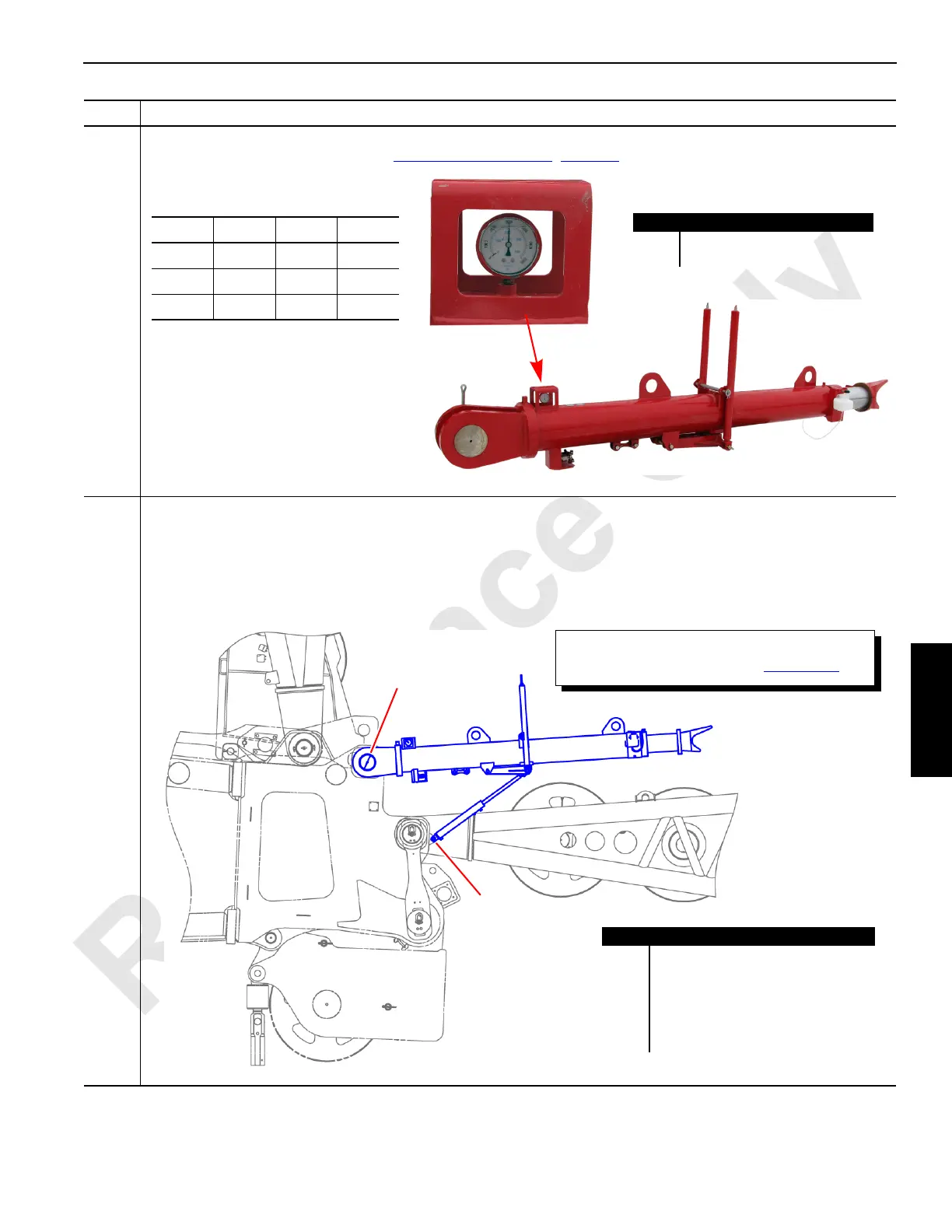
The nitrogen gas pressure gauge (B) on the jib stop assembly (A) should read the pressure shown in the table
below. To increase gas pressure, see Luffing Jib Physical Stop
(page 6-9).
49
Information below from drawing A19443, Sheet 23:
Attach a jib stop assembly (A) to both sides of the #90 boom top (B). The jib stop assembly with the Max UP limit
switch must be installed on the left side of the boom top:
• Connect the jib stop assembly (A) to the #90 boom top (B) with the hinge pins (C) provided.
• Connect the hydraulic cylinders (D) to the #90 boom top (B) with the hydraulic cylinder pins (E) provided.
Step Action
Item Description
A Jib stop assembly.
B Nitrogen gas pressure gauge.
FIGURE 4-48
B
TABLE 1. Jib Stop Pressures
°F °C PSI BAR
80 27 3155 218
70 21 3100 214
60 15.5 3040 210
FIGURE 4-49
A
Item Description
A Jib stop assembly.
B #90 boom top.
C Hinge pin.
D Hydraulic cylinder.
E Hydraulic cylinder pin.
F Spring.
B
C
E
D
The springs (F) are in tension. Tension shall be
removed before servicing (see Figure 4-50
).
F