SET-UP AND INSTALLATION 31000 LUFFING JIB OPERATOR MANUAL
4-52 Published 07-23-15, Control # 078-03
54
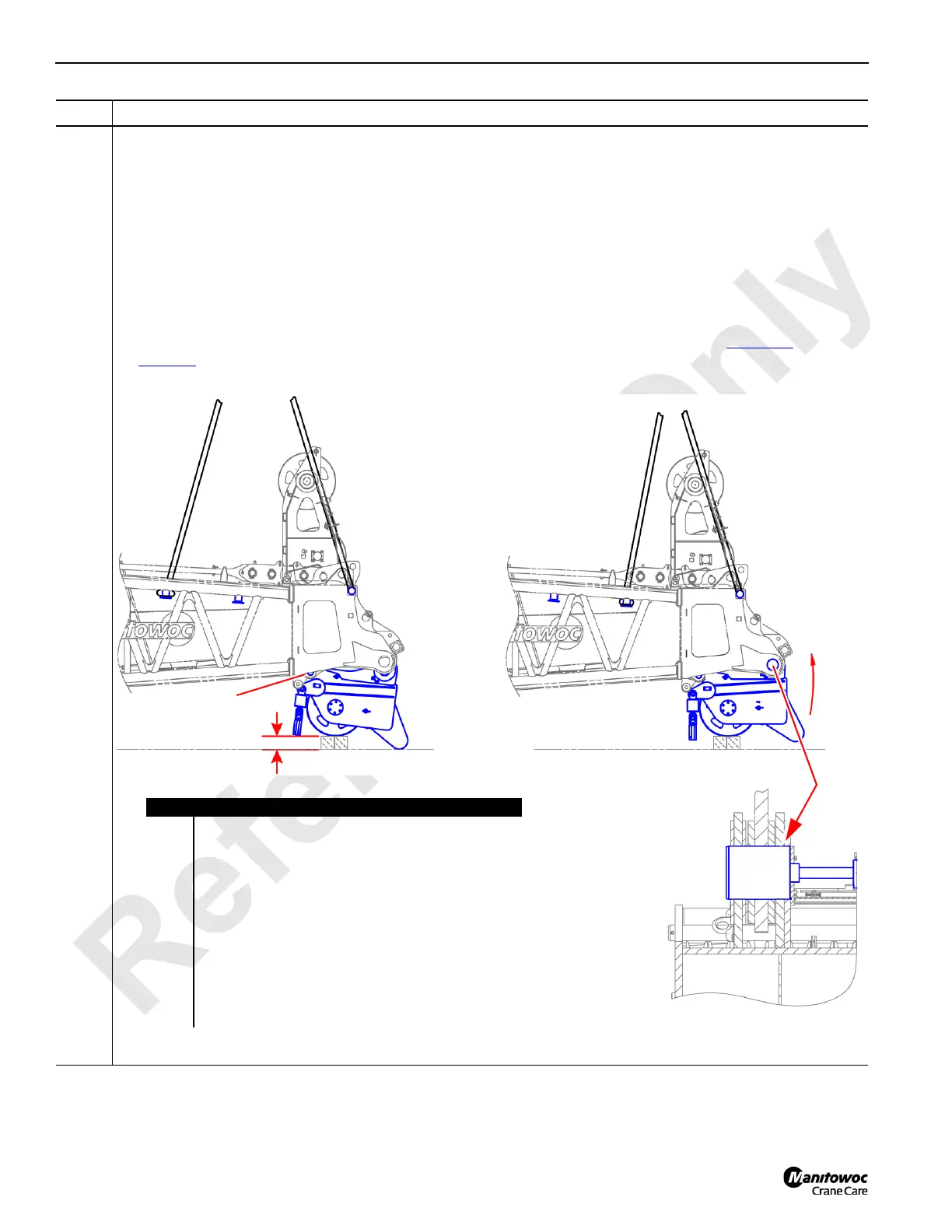
Information below from drawing A19443, Sheet 24:
Boom point right hand lower assembly installation on the #91 luffing jib top:
• Position the right hand lower assembly (E) on the ground with block as shown below.
• Using an assist crane with slings (A) attached at the correct locations (C-C or D-D), position the #91 luffing jib
top (B) onto the right hand lower assembly (E).
• Fasten the rear pins (G).
• Lower the #91 luffing jib top (B) until it is possible to engage the front pins (H) with the pin puller.
• Attach the ISO 46 hydraulic circuit of the Portable Power Unit to the right hand lower assembly (E) and engage
the pins.
• For two drum/lead operation, relocate swivel (I) and socket (J) from the #90 boom top (see Figure 4-8
on
page 4-8
) to the #91 luffing jib top.
Step Action
FIGURE 4-54
Item Description
A Assist crane slings.
B #91 luffing jib top.
C Sling attachment locations when handling a #91 luffing
jib top that has the right hand lower assembly removed.
D Sling attachment locations when handling a #91 luffing
jib top that has the right hand lower assembly attached.
E Right hand lower assembly.
F Blocking height = 30.5 cm (12 in).
G Rear pins.
H Front pins.
I Swivel.
J Socket.
A
A
A
A
C
C
D
D
B
B
E
E
F
G
H
I
J