ENGINE AND ENGINE SYSTEMS 5540F/YB5515 SERVICE MANUAL
6-12 Published 10-21-2010, Control# 198-04
Vaporizer/Regulator Unit
The vaporizer/regulator unit Figure 6-9 receives liquid
propane at tank pressure and reduces the pressure in two
stages to slightly less than atmospheric pressure. When the
engine is cranking or running, a partial vacuum is created in
the fuel line to the throttle body which opens the regulator
allowing fuel flow to the mixer assembly.
In the process of reducing the pressure from upwards of
180 psi (1241 kPa) in the LPG tank to atmospheric pressure,
the liquid propane expands to become a vapor, causing
refrigeration. To compensate for this and to assist in
vaporization, water from the engine cooling system
circulates through the heat exchanger of the vaporizer/
regulator unit. The regulator seals off fuel flow when the
engine stops.
Mixer Unit
The mixer unit Figure 6-9 adjusts the correct amount of fuel
and air for proper engine operation.
The air/fuel mixture is adjusted at the factory for proper
engine operation.
Throttle Body
The throttle body Figure 6-9 houses and operates two fuel
injectors; one for gasoline and one for LPG.
Fuel Tank
The fuel tank is located on the right side of the crane’s frame.
It is a welded box construction with a suction tube installed in
the fuel support port. The tube inhibits sediment and water
from being picked up off the bottom of the tank.
Fuel Level Sender and Gauge
The fuel level sender and gauge are described in Section 11,
Electrical System.
Fuel Pump
The fuel injection pump is located between the fuel tank and
the engine. As long as the dual fuel switch in the cab is set to
“Gasoline,” the fuel pump will pump fuel to the engine when
the ignition switch is turned to the ON position and while the
engine is running. When the dual fuel switch is set to the
LPG position, the pump is shut off.
Types of Fuel to Use
The gasoline operates only on lead-free gasoline with the
following minimum or higher octane ratings:
Anti-Knock Index Number (AKI) -- 87 or 89
Research Octane Number (RON) -- 90
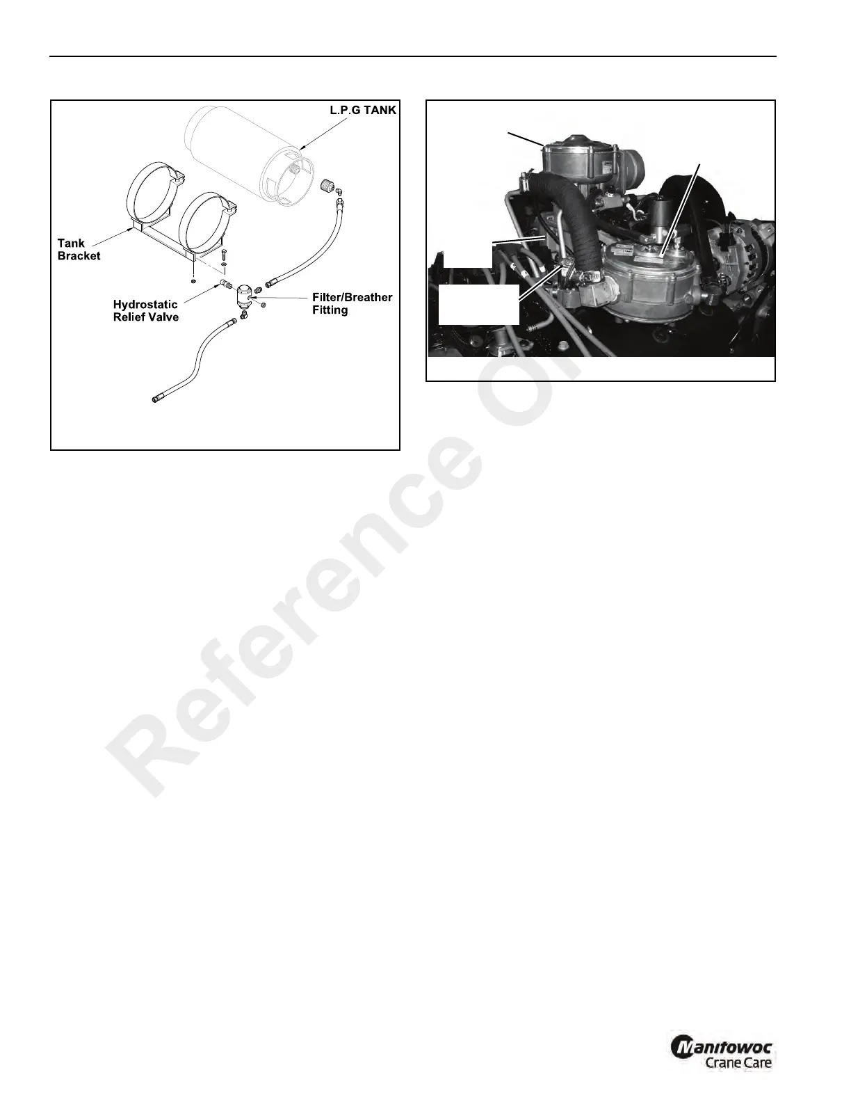
FIGURE 6-8
a2128
Hydrostatic Relief Valve and In-Line Filter
FIGURE 6-9
p3028
Vapor/Regulator
Unit
Mixer Unit
LPG Shutoff
Solenoid Valve
Throttle
Body
Reference Only

 Loading...


