GROVE Published 10-21-2010, Control# 198-04 8-19
5540F/YB5515 SERVICE MANUAL AXLES/DRIVE SHAFTS/WHEELS AND TIRES
REAR AXLES REPAIR
Removal
1. Loosen the wheel lug nuts and raise and support the
machine on axle stands or blocks positioned under the
chassis frame. Remove the wheels.
2. Disconnect the drive shaft from the axle by removing
four bolts and lockwashers.
3. Disconnect and plug the hydraulic hoses to the steering
cylinder.
4. Disconnect, cap and plug the brake hoses from the axle.
5. Support the axle on a trolley jack.
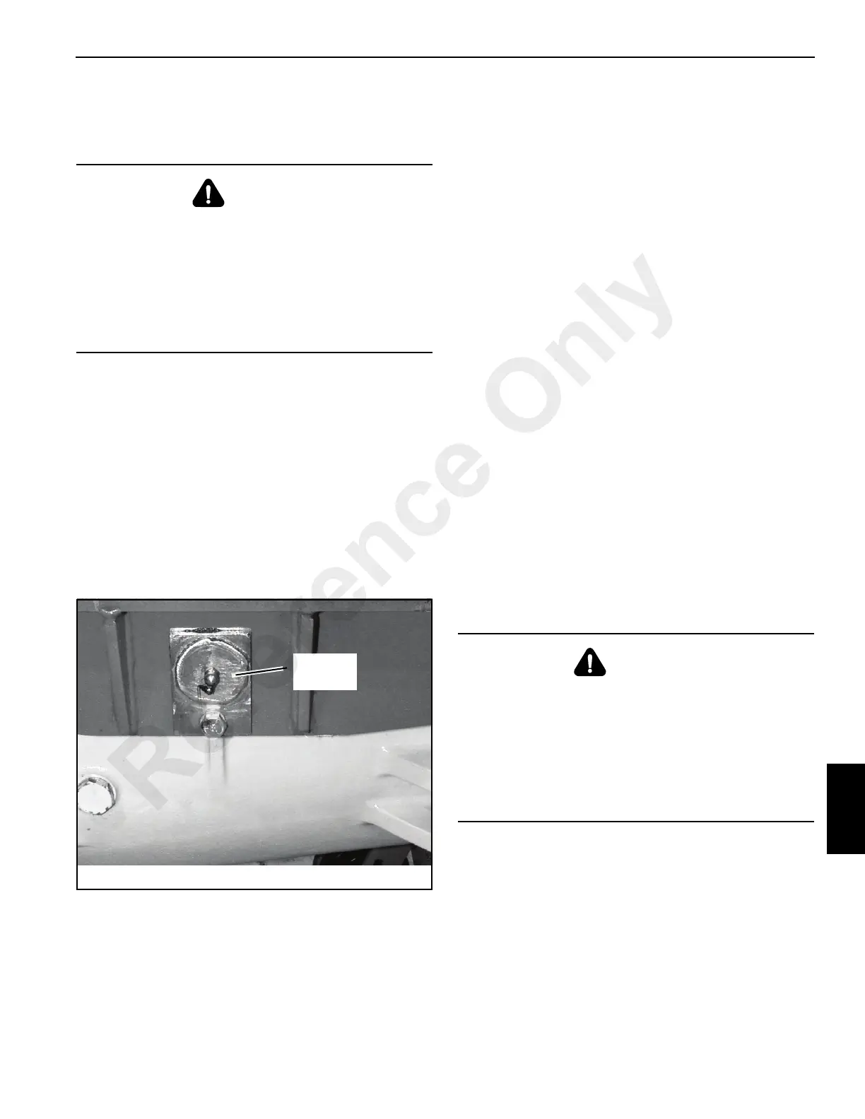
6. Remove the bolt and lockwasher Figure 8-43 securing
the axle pivot pin. Remove the axle pivot pin.
7. Lower the axle clear of the mounting bracket and
remove it from the machine.
Installation
1. Place the axle on a trolley jack and position it under the
machine frame.
2. Raise axle and position it in the mounting frame.
3. Install the axle pivot pin.
4. Coat the threads of the pin retaining bolt with Loctite 242
and then secure the axle pivot pin with the bolt and
lockwasher.
5. Grease the axle pivot pin through two grease fittings.
6. Connect the brake lines and the steering lines to the
axle.
7. Bleed the air from the brake system. See Section 7.
8. Bleed the air from the steering circuit. See Section 8.
Service Tools
To completely the disassemble and assemble the rear axle,
special tools are required. Unless you have the tools
illustrated Figure 8-3, DO NOT service the axle.
Replacing the Pinion Oil Seal
The procedure for replacing the pinion or seal on the rear
drive axle is the same as the front drive axle. Refer to
page 8-6 for replacement procedures.
Axle Hub Repair
Disassembly Figure 8-45
1. Disconnect the track rod and steering cylinders.
NOTE: If the track rod is removed completely, identify R.H.
and L.H. ends to ensure correct assembly.
2. Drain all oil from the hub.
3. Remove screws 33 Figure 8-45.
4. Pry off planet gear carrier 27 at the pry points. Remove
and discard o-ring 32.
WARNING
A raised and badly supported machine can fall on you
causing severe injury or death. Position the machine on a
firm, level surface before raising one end. Ensure that the
other end is securely chocked. Do not rely solely on the
machine hydraulics or outriggers to support the machine
when working under it.
Disconnect the battery cables while you are under the
machine, to prevent the engine from being started.
FIGURE 8-43
p0082
Axle
Pivot Pin
WARNING
A raised and badly supported machine can fall on you
causing severe injury or death. Position the machine on a
firm, level surface before raising one end. Ensure that the
other end is securely chocked. Do not rely solely on the
machine hydraulics or outriggers to support the machine
when working under it.
Disconnect the battery cables while you are under the
machine, to prevent the engine from being started.
Reference Only

 Loading...


