11-21
5540F/YB5515 SERVICE MANUAL STRUCTURALS
make sure it is not obstructed. Also, check the o-rings to
ensure that they are not cut or flattened. Replace if
necessary.
3. The motor and cartridge valve are not serviceable in the
field.
Brake Section
Disassembly
1. Remove the capscrews (Figure 11-34) holding the motor
cover in place. Spring pressure will raise the cover as
the capscrews are loosened. Carefully remove cover
from the brake housing.
2. Remove the springs (Figure 11-35) from the piston and
check them for free height. Each spring should be at
1.200 inches (30.5 mm) with no force on them.
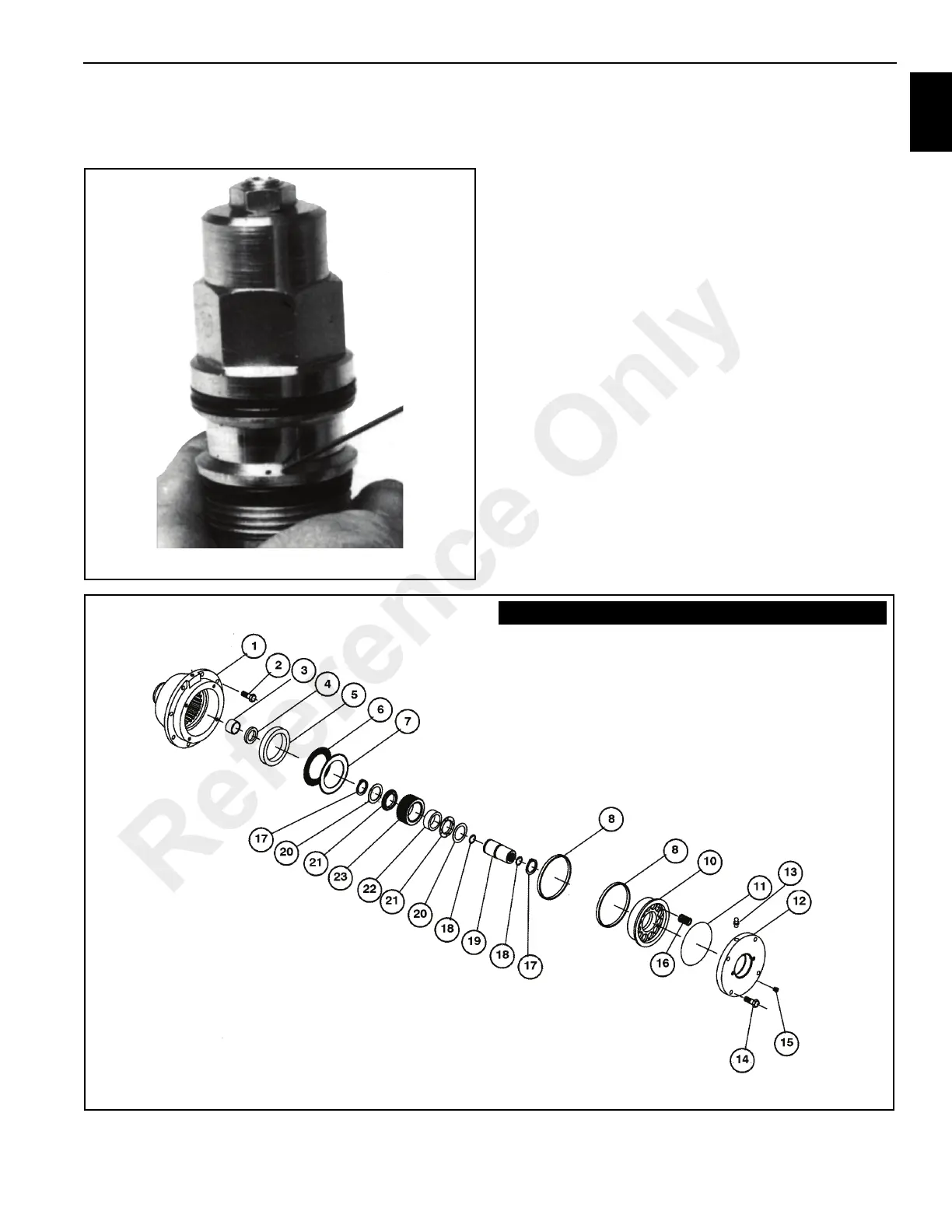
FIGURE 11-33
p0478
Brake Exploded View
Item Description
1. Brake Housing
2. Capscrew (8)
3. Bushing
4. Seal
5. Spacer
6. Friction Disc (7)
7. Stator Plate
8. Seal (2)
10. Piston
11. O-Ring
12. Brake Cover
Item Description
13. Bushing and Breather Kit
14. Capscrew (4)
15. Plug
16. Brake Spring (12)
17. Snap Ring (2)
18. Snap Ring (2)
19. Brake Driver
20. Race (2)
21. Bushing (2)
22. Clutch
23. Input Shaft
Reference Only

 Loading...


