5540F/YB5515 SERVICE MANUAL
9-12 Published 10-21-2010, Control# 198-04
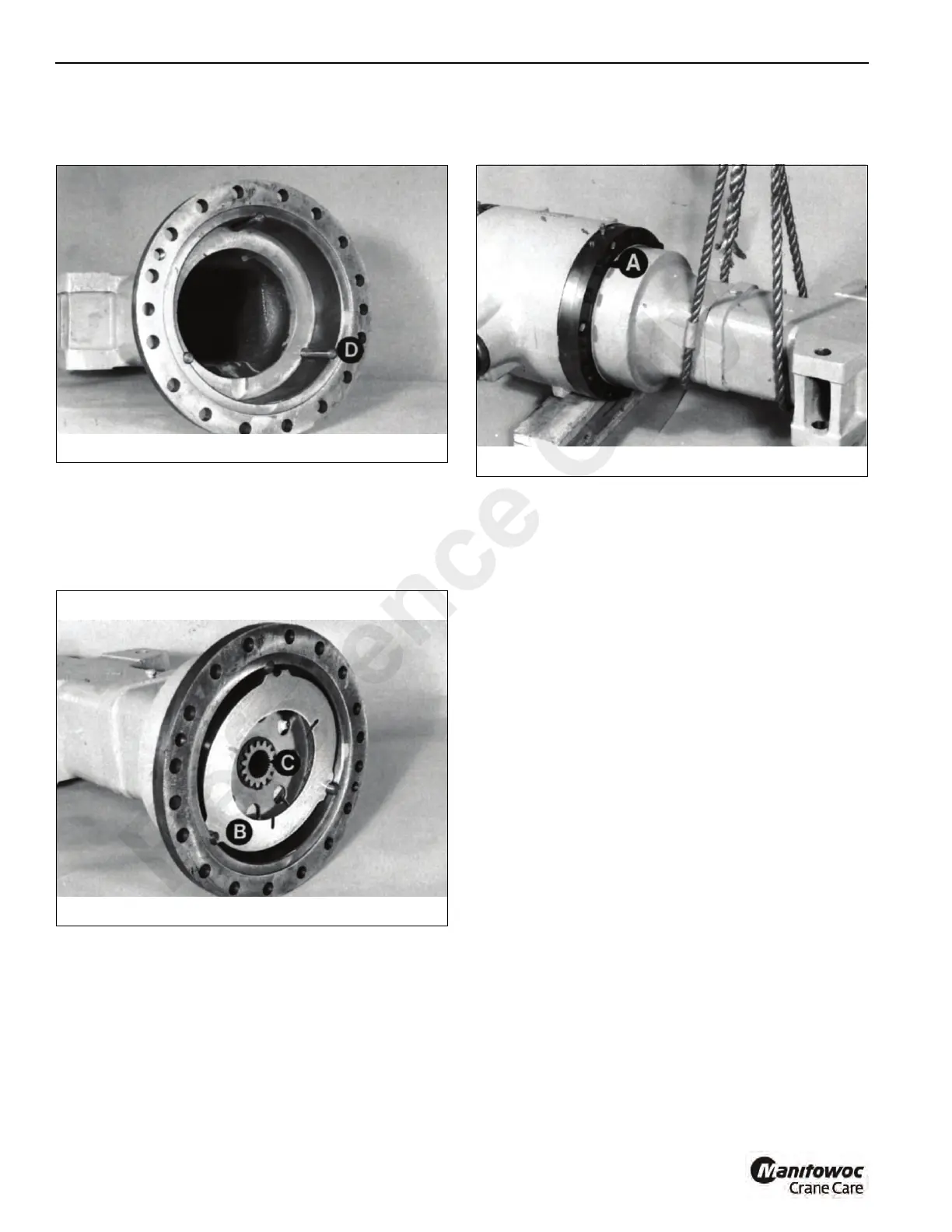
4. Locate the three reaction pins D Figure 9-25 into their
grooves, securing them with grease. Push the pins fully
into their location holes in the housing.
5. Install one counterplate B Figure 9-26 into the housing,
then the brake pack, then the other counterplate. Ensure
that the chamfered end of the brake carrier C faces
away from the drive head. Return reused counterplates
to their original positions. Push the brake pack fully
home.
6. Apply Loctite 275 to the mating face of the drive head.
Locate the axle arm onto the drivehead, with the
embossed word “TOP” on the axle arm up most.
7. Install bolts A Figure 9-27 and tighten to a torque of 178
lb-ft (244 Nm).
NOTE: Check the grade of bolts installed. Grade 8.8
should be tightened to a torque of 178 lb-ft
(244 Nm). Grade 12.9 bolts should be tightened to
a torque of 295 lb-ft (400 Nm).
8. Fill the axle with recommended lubricant. See Section 3,
Preventive Maintenance.
9. Install the axle to the crane’s frame. Refer to Section 6.
Rear Axle Brakes
Refer to Section 6 for Axle Hub Assembly Service. The
service instructions include disassembly, replacement and
assembly of the rear axle brakes.
Reference Only

 Loading...


