STRUCTURALS 5540F/YB5515 SERVICE MANUAL
11-12
22. Install the pin and cotter pin securing the telescope
cylinder bracket to the rear of boom section 2. (Refer to
figure 9-11)
23. Raise up on the boom section 3 assembly and install the
front lower wear pads in the boom section 2.
24. Install the wear pad retainer plates to the front of boom
section 2 and secure with the bolts and lock washers.
25. Install the top rear wear pads on boom section 2.
26. Tighten the front top and bottom side wear pad set
screws on boom section 2 to center the assembly in
boom section 2.
NOTE: Refer to Figure 11-7 for steps 27 thru.
27. As necessary, install the following items on the boom
section 1:
a. Wire rope guide.
b. Boom angle indicator.
c. Anti-two block and LMI components.
d. Jib attachment brackets.
e. Upper rear cable wear pad.
f. Grease fittings and boom pivot pin bushings.
g. Install the front top and bottom side wear pads,
plugs and set screws. Do not tighten set screws at
this time
28. Slide the assembly into the boom section 1.
29. Install the nut, washer, and cotter pin securing the upper
telescope cylinder rod to the rear of boom section 1.
(Refer to figure 9-11)
30. Raise up on the boom section 2 assembly and install the
front lower wear pads in the boom section 1.
31. Install the wear pad retainer plates to the front of boom
section 1and secure with the bolts and lock washers.
32. At the rear of the assembly, install the hoses and fittings
to the telescope cylinder.
33. Tighten the front top and bottom side wear pad set
screws on boom section 1to center the assembly in the
boom section 1.
WIRE ROPE, SHEAVES AND HOIST
BLOCKS
Wire Rope Description
A wire rope is a machine, by definition: "An assemblage of
parts that transmit forces, motion and energy from one to
another in some predetermined manner and to some desired
end."
A typical wire rope may contain dozens, even hundreds, of
individual wires which are formed and fabricated to operate
at close bearing tolerances one to another. When a wire rope
bends, each of its many wires slide and adjust in the bend to
accommodate the differences in length between the inside
and the outside of the bend. The sharper the bend, the
greater the movement.
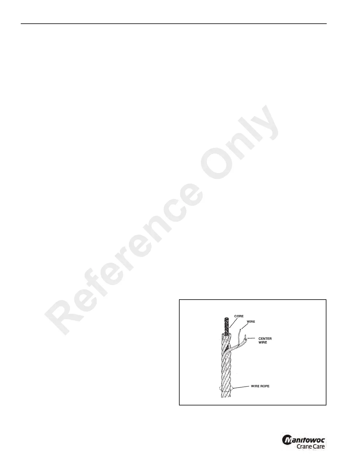
Every wire rope has three basic components (Figure 11-12):
(1) The wires which form the strands and collectively provide
rope strength; (2) the strands, which are laid helical around
the core, and (3) the core, which forms a foundation for the
strands. The core used in the crane wire rope is an
Independent Wire Rope Core (IWRC), which is actually a
smaller rope, or a strand similar to the outer strands of the
rope. The IWRC core adds about 7.5% to the nominal
strength of the wire rope.
The greatest differences in wire ropes are found in the
strands, which may vary widely in the pattern and number of
wires which are laid together.
The wires of the rope may be made of various metals,
including steel, iron, stainless steel, monel, and bronze. The
materials of which wires are made is the primary
determination of rope strength. High-carbon steel is used in
the crane wire rope.
Carbon steel wire ropes come in various grades. The term
“Grade” is used to designate the nominal strength of the wire
rope. The most common grades are Traction Steel (TS),
Plow Steel (PS), Improved Plow Steel (IPS), Extra Improved
Plow Steel (EIPS) and Extra Extra Improved Plow Steel
(EEIPS). The wire rope used on this crane is an EIPS Grade.
One cannot determine the grade of wire rope by its feel or
appearance. To be sure you are using the proper rope,
always obtain the wire rope from your dealer.
Reference Only

 Loading...


